 المقاولين,قاطع الدائرة,الاستشعار,التشفير,بلك,محول

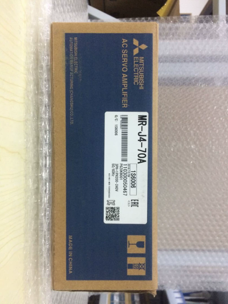

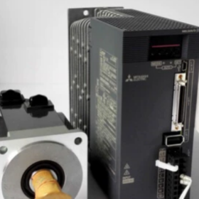
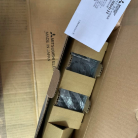
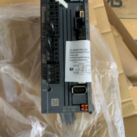
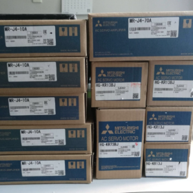
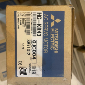
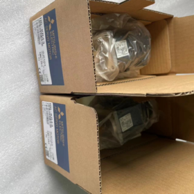
MELSERVO-J4 Series, 750دبليو (0.75 كيلوواط), 200-V class general-purpose pulse-input servo amplifier
تعريف النموذج
MR-J4: ميتسوبيشي 4th-generation servo series
70: قوة المحرك المتطابقة: 750 دبليو
أ: General-purpose interface (pulse + المدخلات التناظرية). Not SSCNET fiber-bus type. Accepts pulse commands from بلك. The -B variant is equipped with SSCNET III/H fiber optic bus interface.
المواصفات الكهربائية الأساسية
| غرض | مواصفة |
| Main‑circuit power input | Single‑phase / Three‑phase AC200‑240 V, 50/60 هرتز |
| Allowable input range | AC170‑264 V |
| تصنيف الانتاج الحالي | 4.0 أ; Peak current: 12 أ (1 s) |
| السيطرة على إمدادات الطاقة | DC24 V ±10%, تقريبا. 0.5 أ |
| Control modes | موضع (الأعلى. input pulse: 4 Mpps), سرعة, عزم الدوران |
| وظيفة السلامة | ستو (إيقاف عزم الدوران الآمن) |
| On‑board components | Built‑in regenerative resistor, Dynamic Brake |
| برامج التكوين | MR‑Configurator2, USB debug port |
المواصفات الميكانيكية
أبعاد: W 60 × H 168 × D 185 mm
وزن: 1.4 كجم
تصاعد: Vertical DIN-rail mounting inside cabinet, IP20
درجة حرارة التشغيل: 0-55 درجة مئوية, لا التكثيف
المحركات المتوافقة (Standard Combinations)
HG-KR73: 750 دبليو, القصور الذاتي المنخفض, بدون فرامل
HG-KR73B: 750 دبليو, القصور الذاتي المنخفض, مع الفرامل الكهرومغناطيسية
HG-SR73: 750 دبليو, الجمود المتوسط
ملحوظة: Amplifier and motor encoder must be matched. MR-J4 drives cannot directly run MR-J3 series motors.
Connector Overview
- CN1: Digital I/O signals, STO safety inputs
- CN2: Servo-motor encoder interface
- CN3: نبض / analog command input (for host PLC)
- CN4: USB debug port for PC parameter setup
- CN5: Analog monitor output
- يو/فولت/ث: Power output to servo motor
التوافق البديل
- Upgrade within same product family
MR-J4-70A → MR-J5-70A (New-generation pulse-type servo). Hardware pin-out is incompatible; program retuning is required.
- Replacement for legacy unit
MR-J3-70A retrofit: MR-J4-70A offers functional compatibility, but mounting dimensions and wiring are not fully interchangeable; cables must be replaced.
- Bus-type comparison
السيد-J4-70A: نبض / analog interface; MR-J4-70B: SSCNET fiber bus. Not direct pin-for-pin replacements.
التطبيقات النموذجية
Engraving machines, ملصقات, material handling mechanisms, معدات التعبئة والتغليف, machine-tool feed axes. Suitable for PLC systems with pulse-output capability.
استكشاف الأخطاء وإصلاحها & ملاحظات الصيانة
- ALM 32: Over-current. Inspect U/V-W motor short-circuit or ground leakage.
- ALM 50: الزائد. Check for mechanical jamming or poor inertia matching.
- AL.E6: Encoder communication failure. Inspect CN2 encoder cable.
- Regenerative overload: Frequent fast acceleration/deceleration requires external regenerative resistor.
Customs HS-code: 8501520000
Complete Installation Guide for Mitsubishi MR-J4-70A
⚠️Safety Warning: All wiring and disassembly must be performed with full power removed. Wait at least 15 minutes until the charge lamp extinguishes. Verify no high-voltage residual exists between P+-N- terminals with multimeter to avoid electric shock. يجب أن يتم تنفيذ العمل من قبل كهربائيين مؤهلين.
السيد-J4-70A: 750 دبليو, 200-V pulse-input servo amplifier, supports single-phase or three-phase AC200-240 V supply.
- Cabinet Mechanical Installation
1.1 بيئة التثبيت
Mount vertically upright inside control cabinet. Do NOT lay flat or install upside-down.
درجة الحرارة المحيطة: 0-55 درجة مئوية, لا التكثيف; Altitude ≤ 1000 m; Free from dust, oil mist and corrosive gas.
طريقة التركيب: Screw fastening or DIN-rail mounting.
1.2 Cooling Clearances (شديد الأهمية)
Top clearance ≥ 50 mm; Bottom clearance ≥ 50 mm; Side clearance ≥ 10 mm
When multiple amplifiers are mounted side-by-side, reserve sufficient cooling space. Keep away from heat-generating components such as contactors and resistors.
Do not block intake and exhaust vents with cables or trunking.
1.3 Fastening Procedure
- Ensure cabinet back-plate is flat and burr-free.
- Fit amplifier against back-plate and tighten four mounting screws.
- Avoid heavy impact on the housing to prevent internal component damage.
- Step-by-Step Wiring
Terminal definitions for MR-J4-70A
L1, L2, L3: Main-circuit power input. For single-phase 220 V operation: connect L1 & L2; leave L3 unconnected.
L11, L21: Control-circuit power AC200-240 V
يو/فولت/ث: Power output to servo motor
P+, N-: Regenerative resistor terminals; factory short-circuit jumper fitted for built-in resistor
بي: الأرض الواقية
CN1: Digital I/O and STO safety signals
CN2: Encoder plug for HG-KR73 / HG-SR73 motor
CN3: Pulse command I/O connected to PLC pulse output
CN4: Mini-USB debug port for MR-Configurator2 PC software
Step 1: Protective Earth (بي)
Connect amplifier PE terminal and motor PE to cabinet protective earth busbar. Earth resistance ≤ 10 Ω. Perform earthing first.
Step 2: Power-circuit Wiring
- Main-circuit power L1/L2/L3
Three-phase AC200-240 V: Wire L1, L2 and L3.
Single-phase AC200-240 V: Connect L1 and L2; L3 must remain open.
Install circuit-breaker and contactor upstream. Never feed mains voltage into U/V-W output terminals.
- Control-circuit power L11, L21: AC200-240 V. May share supply with main circuit.
ملحوظة: Main circuit and control circuit can be supplied separately. For signal-only debugging, energize only L11/L21; amplifier powers up without main motor voltage.
- Regenerative resistor configuration:
Normal start-stop duty: Retain factory short-circuit jumper between P+-D to use internal regenerative resistor.
Frequent rapid acceleration/deceleration: Remove jumper and fit external regenerative resistor between P+ and N-, select correct resistance and power rating.
Step 3: Motor Power Cable U/V/W
Connect amplifier U-motor U; V-motor V; W-motor W one-to-one. Do NOT swap phases. Do not insert contactor, capacitor or surge suppressor between amplifier and motor.
Motors with electromagnetic brake: Brake coil requires independent 24 VDC supply. Brake release logic shall be controlled via external relay. Do not power brake from servo drive.
Step 4: Encoder Cable CN2
Use dedicated MR-J4 encoder cable. Fully insert CN2 connector and lock latch. Route encoder cable away from power cables. Avoid sharp bending or pulling. MR-J3 encoder cables are NOT compatible with MR-J4 drives.
Step 5: Digital I/O CN1 & Pulse Interface CN3 (Position-pulse control)
- EM2 (Forced stop / توقف اضطراري): Hardware safety signal. Hard-wire emergency stop for operational machines. Short-circuit only for temporary bench testing.
- SON (Servo-On), RES (Alarm reset), LSP (Forward stroke limit), LSN (Reverse stroke limit).
- CN3 pulse command: Select PULSE+SIGN format to match PLC output configuration.
Separate signal cables from power cables by ≥ 10 cm to reduce noise interference. Use shielded signal cables with single-end shield grounding.
Step 6: Debug Interface CN4-USB
Connect Mini-USB cable between PC and CN4. Install MR-Configurator2 software for parameter backup, JOG operation and alarm diagnostics.
- Mandatory Pre-Power-On Check-List (Perform with power OFF)
- Multimeter measurements:
No short-circuit between L1-L2-L3 and L11-L21.
Good insulation; no short-circuit phase-to-phase or phase-to-ground on U/V-W motor output.
No short-circuit across P+ and N- محطات.
- Wiring verification:
Confirm mains supply is NOT connected to U/V-W output terminals.
U/V-W phases correctly matched; encoder connector latched; PE earthing solid.
Regenerative resistor jumper / external resistor fitted correctly; brake wiring verified.
- Mechanical inspection:
Coupling securely tightened; no mechanical binding; no mechanical collision risk. Implement anti-fall protection for vertical axes.
- Safety loop: Emergency-stop circuit confirmed functional.
- Power-Up Sequence
- Keep personnel clear of moving mechanisms; position machine at safe location.
- Energize control power L11/L21 first. Confirm amplifier powers on without alarms.
- Close main-circuit power L1/L2/L3.
- If alarms appear: Troubleshoot according to alarm codes (AL 32 over-current, AL.E6 encoder error, AL 50 overload).
- Connect PC software and back-up factory parameter set.
- Debug workflow:
- Run low-speed JOG via software, verify motor rotation direction.
- Validate forward / reverse limit signals.
- Configure pulse format and electronic gear ratio to match PLC.
- Test positioning with small-volume pulse commands; gradually increase travel.
- Run full-cycle motion and execute One-Touch-Tuning for servo gain optimization.
- مخاطر التثبيت الشائعة
- Single-phase supply: Do not connect voltage to L3 terminal.
- Applying AC220 V power to U/V-W will permanently destroy amplifier.
- Loose encoder CN2 connector causes intermittent AL.E6 encoder fault.
- Powering motor brake directly from servo drive results in brake-release failure.
- Insufficient cooling clearance leads to thermal alarm AL 51 under continuous operation.
- EM2 emergency-stop left un-wired prevents servo-on operation.
- Parallel routing of power and signal cables causes pulse noise and positioning loss.
- صيانة
Periodically re-tighten terminal screws; keep cabinet dust-free. Export and save servo parameter files annually.
Storage conditions: -20 ~ +65 °C, لا التكثيف.
Complete Parameter Tuning Procedure for Mitsubishi MR-J4-70A
MR-J4-70A pulse-input servo amplifier. Tuning tool: MR-Configurator2 (Mini-USB cable connected to CN4).
⚠️Before tuning: Confirm machine is mechanically free of jamming; keep personnel clear of moving parts. After parameter modification, write parameters to EEPROM for non-volatile storage. Parameters groups: PA-Basic parameters, PB-Gain & Filter, PC-Extended parameters, PD-I/O assignment parameters.
- Software Connection & الاستعدادات
- Connect PC Mini-USB to CN4. Power on drive. Launch MR-Configurator2, go online, read all parameters and save parameter backup file.
- Factory reset (خياري): Unlock write-protection via PA19, perform parameter reset, cycle power for changes to take effect.
- Confirm motor identification: Verify connected motor HG-KR73 / HG-SR73 is correctly recognized in software monitor screen; no motor-mismatch alarm.
- Basic Control Parameters (Position Pulse Mode Most-Used)
PA-Group (Basic Setting Parameters)
| Parameter No. | اسم | وصف | Typical Setting |
| PA01 | Operation mode selection | 1000 = Pulse position control; 0001 = Speed; 0002 = Torque | 1000 (Pulse positioning) |
| PA13 | PLSS Command pulse input format | Match PLC pulse output format | Must match PLC configuration |
| 0100: PULSE+SIGN (نبض + Sign, الأكثر شيوعا) | |||
| 0001: CW/CCW dual‑pulse | |||
| 0002: A/B phase quadrature pulse | |||
| PA06 CMX | Electronic gear numerator | CDVCMX=Number of PLC pulses per motor revolutionMotor encoder resolution(4194304) | Calculated per mechanical setup |
| PA07 CDV | Electronic gear denominator | ||
| PA10 | INP In‑position range | Position‑complete output window, وحدة: command pulses | 50‑200, adjust for accuracy requirements |
| PA11 | Command pulse filter | 0 for differential‑line driver input; set to 1 for open‑collector input | 0 (إشارة تفاضلية) |
| PA19 | Parameter write inhibit | 0000: Full parameter modification permitted; enable write‑lock after commissioning | 0000 during debugging |
✅Electronic-gear example: Ball-screw lead 10 mm, direct motor coupling. Require 10000 PLC pulses per full motor rotation.
Encoder resolution: 4194304 (22-قليل)
CMX/CDV = 4194304 / 10000 → CMX=4194304, CDV=10000
Hardware note: Differential input max. 4 Mpps; open-collector max. 200 kpps. Use differential signaling for high-speed operation.
- PD-Group Digital I/O Parameters
- PD01-PD14: Input terminal assignment (CN1)
SON (Servo-On), LSP (Forward stroke limit), LSN (Reverse stroke limit), RES (إعادة ضبط), EM2 (توقف اضطراري).
EM2 hardware emergency-stop must be hard-wired. Short-circuit connection permitted only for temporary bench-test; never for production equipment.
- PD20-PD27: Output terminal assignment: ALM (إنذار), أردي (Servo Ready), INP (In-position complete).
- Power-On & JOG Test (PLC connection not required, motor validation first)
- Software → Test Operation → JOG operation.
- Set low speed 50-200 r/min, jog forward and reverse.
- Confirm rotation direction. If direction reversed: invert setting of PA14 Rotation direction selection.
- Check for abnormal noise, vibration and mechanical binding.
Complete JOG validation before connecting PLC pulse commands.
- Servo Gain Tuning (Critical for vibration, overshoot and positioning time)
Three tuning methods for MR-J4: One-Touch Tuning (Recommended first-choice), Real-Time Auto-Tuning, Manual PB-parameter fine-tuning.
الطريقة1: One-Touch Tuning (Recommended for commissioning)
- Complete mechanical assembly with real-world load fitted.
- Software menu Tuning → One-Touch Tuning.
- Set target response level: 1-15
High-rigidity light-load machine: 8-12
Timing-belt / low-rigidity mechanism: 3-7
- Execute procedure; servo performs reciprocating test motion to estimate load inertia and auto-set gains and filters.
- Write result to EEPROM after completion.
- Run positioning cycles; evaluate vibration, over-shoot and acoustic noise.
الطريقة2: Real-Time Auto-Tuning
Set PA08 tuning mode to `_ _ _1`. Servo continuously estimates load inertia and dynamically adjusts gain during actual machine operation. Suitable for variable-load conditions.
الطريقة3: Manual PB-Parameter Fine-Tuning (Refine when One-Touch result is unsatisfactory)
| المعلمة | اسم | وظيفة |
| PB06 | Load‑to‑motor inertia ratio | Load inertia / motor inertia. Auto‑calculated by One‑Touch‑Tuning; can be manually entered. |
| PB07 | Position loop gain PG1 | Higher value speeds positioning; excessive gain causes oscillation |
| PB08 | Speed loop gain VG1 | Determines dynamic response; higher improves tracking performance |
| PB09 | Speed loop integral time VI | Smaller value strengthens integral action, increases tendency to oscillate |
| PB13 | Low‑pass filter | Suppress high‑frequency mechanical resonance |
| PB01 | Adaptive vibration suppression filter | Set 1 to enable automatic resonance suppression |
Manual tuning sequence: Tune speed-loop parameters first, then position-loop. If oscillation occurs, immediately reduce gain values; do not increase gain blindly.
Symptom-based correction table
- Buzzing vibration at stand-still: Reduce PB07 position-loop gain; enable PB01 adaptive filter, configure notch filter.
- Position over-shoot: Lower position-loop gain; increase speed-loop integral time.
- Slow response and long settling time: Moderately raise PG1 and VG1.
- Fixed-frequency abnormal noise: Use software Machine Analyzer function to scan resonance frequency and configure notch filter.
- Limit, Home-Return & Torque-Limit Parameters
- PA12 Torque limit: Range 0-100%. Set to 50% during commissioning to prevent mechanical collision damage.
- PC01-PC06: Homing parameters; home-return mode, homing speed, creep speed, home offset value.
- PC13, PC14: Soft-limit position thresholds (وحدة: command pulses).
- Parameter Upload / تحميل & Saving
- After modification, execute Write to EEPROM in software. Changes stored in RAM only will be lost on power-cycle.
- Upload: Read servo parameters and save project file. For amplifier replacement, download saved parameter file for fast commissioning.
- Standard Commissioning Test Sequence
- JOG jog test; confirm rotation direction and no mechanical binding.
- Send small-volume pulse commands from PLC, verify travel distance via electronic-gear ratio calculation.
- Low-speed reciprocating motion; check for noise and vibration.
- Execute One-Touch-Tuning.
- Mid-speed and full-speed positioning cycles; monitor in-position status, over-shoot and residual vibration.
- Functional test of travel limits, emergency-stop and alarm-reset.
- After full validation, save complete parameter backup.
- Common Commissioning Faults
- Motor does not rotate, أردي (Servo Ready) output ON: Check SON (Servo-On) إشارة, EM2 emergency-stop loop and PA01 operation-mode setting.
- Motor rotates but travel distance is incorrect: Verify PA13 pulse-input format and CMX/CDV electronic-gear ratio calculation.
- الاهتزاز والضوضاء غير الطبيعية أثناء التشغيل: Incorrect inertia-ratio setting, excessive gain, mechanical resonance. Prioritize One-Touch-Tuning plus Machine-Analyzer tool.
- AL 50 Overload alarm: Excessive load-inertia ratio, high mechanical friction, gain values too high.
- AL.E6 Encoder alarm: Damaged or poorly-seated CN2 encoder cable.
HS-code for customs: 8501520000





NH42-63-318x560.png "مفاتيح النقل التلقائي من نوع الكمبيوتر الشخصي CHINT (المنشطات الأمفيتامينية)NH42-63/4SZ")



