 المقاولين,قاطع الدائرة,العاكس للطاقة الشمسية,عداد كهرباء,البطاريات الشمسية

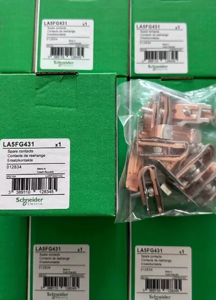


LA5FF431 is a 3-pole main contact repair kit belonging to شنايدر إلكتريك TeSys F series. It is a consumable replacement accessory for AC المقاولين, specially designed for medium & low current contactors in F series. It is used for replacement and maintenance after contact wear or ablation, to restore the breaking capacity and electrical service life of contactors. Each complete kit contains 3 moving contacts, 6 fixed contacts, matched arc extinguishing components, spring plates and fixing screws. Widely applied in industrial automation, motor control and power distribution maintenance scenarios.
- انهيار رمز النموذج
LA5: Main product category code, representing contactor main contact assembly (main contact repair kit)
FF: Specification matching code, corresponding to TeSys F series contactors with 115A / 150A current rating
431: Structural specification identifier, stands for 3-pole main contact configuration
- المعلمات التقنية الأساسية
| عنصر المعلمة | Specification Value |
| نوع المنتج | Contactor Main Contact Repair Kit |
| عدد البولنديين | 3 أقطاب |
| Matched Rated Current | 115أ / 150أ |
| تصنيف جهد التشغيل | 660الخامس و |
| طريقة التركيب | Screw fastening |
| نوع المحطة | Screw-clamped terminals |
| Standard Tightening Torque | 3.6 N路m (32 lb.in) |
| Net Weight per Unit | تقريبا. 0.27 كجم |
| Packing Weight | تقريبا. 345 ز |
| رمز النظام المنسق | 85389099 |
- Compatible Contactor Models
Schneider Original Series: LC1F115 series, LC1F150 series, CR1F150 series contactors
Domestic Compatible Models: NC2-115/150, GSC2-115F/150F, CJX2-115F/150F and other AC contactors of equivalent specifications
- Cross Reference of Contact Kits for TeSys F Series Same Current Ranges
| Contact Model | Matched Contactor Model | Matched Current Rating | البولنديين |
| LA5FF431 | LC1F115, LC1F150 | 115أ / 150أ | 3ص |
| LA5FG431 | LC1F185, LC1F225 | 185أ / 225أ | 3ص |
| LA5FH431 | LC1F265 | 265أ | 3ص |
| LA5FJ431 | LC1F330, LC1F400 | 330أ / 400أ | 3ص |
| LA5FK431 | LC1F500 | 500أ | 3ص |
| LA5FL431 | LC1F630 | 630أ | 3ص |
- تثبيت & احتياطات السلامة
- Mandatory Safety Rule: Cut off all power supplies of the contactor thoroughly before replacement, perform voltage verification to prevent electric shock and arc flash hazards.
- Inspect contact springs and arc chute plates simultaneously during replacement. Replace them together if springs lose elasticity or arc chutes are damaged, to avoid deterioration of breaking performance.
- Tighten fixing screws to the standard torque of 3.6 ن · م. Insufficient torque causes overheating at contact points; excessive torque leads to thread stripping.
- Complete no-load test of contactor closing and opening after replacement. Do not energize for operation until smooth movement and tight contact fitting are confirmed.
- الأخطاء الشائعة & استكشاف الأخطاء وإصلاحها
| ظاهرة الخلل | السبب الجذري | Remedial Measures |
| Abnormal temperature rise after contactor closing | Excessive contact wear, oxidized contact surfaces, loose fixing screws | Check contact abrasion; replace full set if service life limit is reached; clean contact surfaces; retighten screws to specified torque |
| Severe arcing & slow arc extinction during breaking | Ablated contact surfaces, overload current exceeding rated value | Verify load current matches contactor rating; fully replace contacts if ablation depth exceeds limit; prohibit reuse after simple grinding only |
| دائرة مفتوحة & high voltage drop after closing | Stuck contact guide rails, failed contact springs | Remove foreign debris from contact guide parts; replace spring assembly if spring elasticity declines |
Step-by-Step Installation Guide for LA5FF431 Main Contact Kit
- Pre-Work Preparation (Mandatory Safety Prerequisite)
1.1 Mandatory Safety Confirmation
Fully disconnect all power on both incoming and outgoing sides of the contactor, hang “No Closing” warning sign, use voltage tester to confirm zero voltage on main circuit and control circuit. Wear insulating gloves and goggles throughout the operation to guard against arc flash and electric shock risks.
1.2 Required Tools
Torque screwdriver (range covering 3.6 ن · م), Phillips screwdriver, flat screwdriver, soft brush, anhydrous ethanol, clean non-woven cloth, digital multimeter, لا.0 fine sandpaper (only for emergency treatment of old contacts; forbidden for new contacts).
1.3 Material Inspection
Unpack and count components of LA5FF431 kit: 3 moving contacts, 6 fixed contacts, matched contact springs, fixing screws and spare arc chute plates. Confirm contact surfaces are free of collision marks and oxidation, and all accessories are complete before starting work.
- Removal Procedure of Old Contacts (Operate Phase by Phase to Avoid Mix-Up)
- Remove External Accessories & الأسلاك
Take off fixing buckles/screws of contactor arc chute first, place the whole arc chute on a clean workbench; mark phase labels for 3-phase main circuit wires, remove incoming and outgoing terminals with phase marks to prevent reversed wiring later.
- Dismantle Fixed Contacts
Loosen fixing screws of fixed contacts phase by phase with screwdriver, take out upper and lower sets of fixed contacts and collect old screws uniformly. Distinguish mounting orientation of incoming-side and outgoing-side fixed contacts and record original installation direction.
- Dismantle Moving Contact Assembly
Press the contactor moving core to maintain closed state, remove circlips/locating pins of 3-phase moving contacts one by one, pull out moving contacts and matched springs. Record installation direction and compression state of springs to avoid reversed assembly of new parts.
- Internal Cavity Cleaning
Clear metal dust and arc ablation debris inside the contactor with soft brush; wipe contact mounting base and guide rails with anhydrous ethanol soaked non-woven cloth to eliminate oil stains and foreign residues.
- Installation Procedure of New Contacts (Strict Phase Matching, Diagonal Tightening)
- Install Moving Contact Assembly
Fit new springs onto moving contact mounting seats following original disassembly direction, clip moving contacts into guide grooves, reinstall locating pins/circlips for fixation. Verify each phase individually: moving contacts slide smoothly along rails without jamming, springs deliver uniform elasticity and contacts retain normal overtravel allowance.
- Install 3-Phase Fixed Contacts
Fit fixed contacts against mounting base in original orientation. After inserting fixing screws, pre-tighten diagonally first, then fasten all screws to 3.6 N·m with torque wrench. Do not fully tighten one side at a time to prevent contact tilt and poor contact.
يلاحظ: New contact surfaces are pre-coated with silver alloy plating. Grinding and scraping are strictly forbidden, as damaged plating will drastically shorten electrical service life.
- Reinstall Arc Chute
Check arc chute plates for breakage and looseness, clip arc chute back to the contactor at original position and fasten fixings tightly. Ensure the arc chute fully covers contact area without misalignment or gaps.
- Restore Main Circuit Wiring
Reconnect incoming and outgoing wires according to phase labels, tighten terminal screws to corresponding rated torque to guarantee tight fit between wiring terminals and fixed contact end faces.
- Pre-Energizing Inspection & Acceptance
4.1 Mechanical Characteristic Verification
Manually push contactor moving core to full closed position and repeat 3–5 times for confirmation:
Smooth movement without jamming, no abnormal noise during closing and opening
Simultaneous contact of 3-phase contacts without phase delay (test each phase via multimeter continuity mode)
Complete disconnection of contacts after release, no adhesion or abnormal clearance
4.2 Electrical Performance Test
Measure contact resistance of 3-phase main circuit with low-resistance range of multimeter. Resistance values of three phases shall be roughly consistent with deviation ≤10%, and single-group contact resistance ≤100μΩ.
4.3 No-Load Energized Test
Switch on control circuit power and perform 5–10 times of no-load make-break tests. Confirm reliable closing, crisp opening, no coil overheating or abnormal vibration. Cut off control power after test and complete final acceptance.
- Strictly Prohibited Operations (Safety Red Lines)
- Contact replacement with live power is forbidden; operation with only single-pole power disconnected is prohibited.
- Replacing only 1 أو 2 phases of contacts is forbidden; full 3-phase set must be replaced together to prevent motor single-phase operation caused by uneven 3-phase contact resistance.
- Grinding or filing new contact surfaces to damage silver alloy plating is strictly prohibited.
- Tightening with non-rated torque or ordinary screwdrivers by subjective feel is forbidden, to avoid contact overheating or thread stripping.
- Operation without arc chute or with damaged arc chute is forbidden, which leads to unextinguished breaking arc and further short circuit or fire hazards.
- Post-Commissioning Inspection Reminders
Recheck temperature rise of terminals and contact parts 24 hours after commissioning. Normal operating temperature shall not exceed ambient temperature +60K. Retighten all fasteners after 7 days of operation to eliminate initial stress relaxation.


 مسلسل. It is a standard model with 200V voltage class, matching 2kW-class servo motors. Equipped with dual command interfaces of pulse train and analog voltage, it supports full-mode control including position,")
. It is a mid-range CPU with outstanding cost performance in the S7-1200 product line. Integrated with native digital I/O and analog inputs")
")


")
NH42-63-318x560.png "مفاتيح النقل التلقائي من نوع الكمبيوتر الشخصي CHINT (المنشطات الأمفيتامينية)NH42-63/4SZ")


