 contactor,cortacircuitos,sensor,Codificador,SOCIEDAD ANÓNIMA,Convertidor

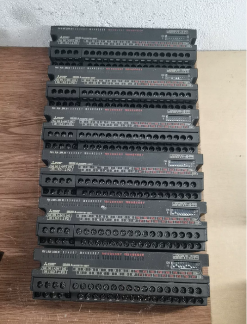

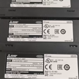
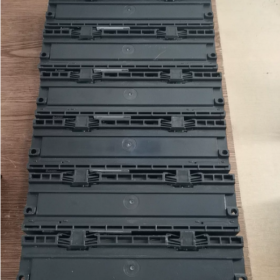
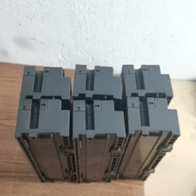
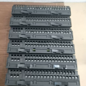
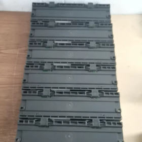
- Definición del modelo & Posicionamiento del producto
AJ65SBTB1-32DT: Compact Screw Terminal Block Type Remote Mixed I/O Module for CC-Link
AJ65SB: CC-Link Remote I/O Serie
TB1: Integrated screw terminal block (finger touch protection type)
32: Total 32 puntos de E/S (16 entradas + 16 salidas)
D: Entrada de 24 V CC.; t: Sink Transistor Output
Ocupa 1 CC-Link station number, no multi-station allocation required. Compatible with Q/L/R series CC-Link master stations (p.ej., QJ61BT11N)
- Especificaciones eléctricas básicas
2.1 Input Section (16-point DC24V Positive Common / Sink Input)
| Artículo | Especificación |
| Number of Points | 16 agujas (X0 ~ X15) |
| Tensión nominal | CC 24 V, allowable range 19.2~26.4V (ripple ≤5%) |
| Input Current per Point | Aprox.. 7mamá |
| ON Threshold | ≥14V / ≥3,5 mA |
| OFF Threshold | ≤6V / ≤1,7 mA |
| Tiempo de respuesta (OFF ↔ ON) | ≤1.5ms |
| Aislamiento | Aislamiento del optoacoplador |
| Método de cableado | Positive common terminal (COM connected to +24V, sensor negative wire connected to input terminals) |
2.2 Output Section (16-point Sink Transistor Output)
| Artículo | Especificación |
| Number of Points | 16 agujas (Y0 ~ Y15) |
| Load Voltage | DC19.2~26.4V |
| Max Current per Point | 0.5un/punto; Total current per COM: 3.6A |
| Corriente de irrupción | ≤1A (duration ≤10ms) |
| OFF-State Leakage Current | ≤0.25mA |
| ON-State Voltage Drop | ≤0.3V (at 0.5A load) |
| Tiempo de respuesta | ≤0,5 ms |
| Lógica de salida (Hundir) | Connect load negative pole to output terminals; connect load positive pole to external +24V |
2.3 Fuente de alimentación del módulo
Voltaje de suministro: DC20.4~26.4V
Overall Power Consumption: ≤60mA (all I/O points switched ON simultaneously)
- Mecánico & Parámetros ambientales
- Dimensiones generales: W179mm × H50mm × D40mm
- Peso: 0.25kilos
- Terminales: tornillos m3; 7-pin communication & power split terminal + 34-pin I/O terminal block
- Clase de protección: IP2X (terminals with finger electric shock protection; direct mounting on machine tools allowed)
- Temperatura de funcionamiento: 0~55°C; Temperatura de almacenamiento: -20~75°C
- Humedad: 10~90% HR, sin condensación
- Tensión soportada: AC500V for 1 minute between external DC terminals and ground; Resistencia de aislamiento ≥10MΩ (tested at 500VDC)
- Key CC-Link Network Wiring Guidelines
- Bus Topology: Daisy-chain wiring; 120Ω terminating resistors must be fitted at both bus ends
- Communication Cable: Dedicated CC-Link shielded twisted pair cable
- Longitud máxima del autobús: 1.2kilómetros (10Mbps high-speed mode)
- Station Address: Set via DIP switches on module side (station No. 1~64)
- Definición de terminal: DA/DB communication lines, DG shield ground, 24V module power supply, FG frame protective earth
- Series Model Differentiation (DT / DT1 / DT2)
AJ65SBTB1-32DT: Modelo estándar; 7mA input current, max 3.6A total output current per COM
AJ65SBTB1-32DT1: Low-current input (5mamá), suitable for 2-wire proximity sensors
AJ65SBTB1-32DT2: Improved response model; grouped current limiting for output COMs, enhanced anti-interference performance
- Escenarios de aplicación típicos
- Distributed field signal collection for production lines, packaging machines and injection molding machines
- Remote control of sensors and solenoid valves mounted adjacent to machine tools
- CC-Link slave station expansion for large production lines to reduce cabinet internal wiring
- Digital remote I/O slave stations for logistics sorting and conveyor lines
- Alambrado & Prohibiciones de instalación
- All input COM terminals must be uniformly connected to +24V; mixing ground potentials from separate power supplies is forbidden
- Transistor outputs cannot directly drive AC loads; external relays are mandatory
- Fit freewheeling diodes in parallel across inductive loads (válvulas solenoides) to prevent transistor breakdown
- CC-Link bus shielding layer single-point grounding; grounding at both ends is prohibited
- Recommended terminal wire gauge: AWG14~16; screw tightening torque: 0.8~1.0N·m
Instalación completa & Operation Manual for AJ65SBTB1-32DT MITSUBISHI CC-Link Remote I/O Module
- Hardware Structure Description (Module Front Panel)
1.1 Indicadores LED de estado
| LED Label | Estado normal | Indicación de falla |
| PW | Encendido fijo | DC24V module power normal; OFF = No power supply |
| CORRER | Encendido fijo | CC-Link communication normal; OFF = Communication interruption |
| ERRAR | APAGADO | comunicación normal; Encendido fijo / Flashing = Fault detected |
| X0~XF / Y0~YF | Corresponding LED lights up | Respective input/output channel activated |
1.2 DIP Switch Banks (2 Groups)
Station No. Switches: Tens digit (40/20/10), Units digit (8/4/2/1). Sum values to set unique station number 1~64
Communication Speed Switches (VELOCIDAD): 3-position switches (4/2/1) to configure CC-Link bus transmission speed
1.2 Terminal Block Split Layout
① 7-pin bus terminals: Y, DB, Director General, 24V+, 0V-, FG (comunicación + module power supply)
② 34-pin I/O terminals: X0~X15 inputs, Y0~Y15 outputs, Input COM, Salida COM
1.3 Pestillo de carril DIN
Spring latch at bottom, compatible with standard TH35 DIN rails
- Procedimientos de instalación mecánica
2.1 Installation Environmental Requirements
Temperatura de funcionamiento: 0~55°C; Avoid direct sunlight, polvo, niebla de aceite, condensation and heavy vibration zones
Heat Dissipation Clearance: Reserve ≥10mm gap above and below module; do not mount close to heat-generating contactors or transformers
Orientación de montaje: Horizontal DIN rail mounting preferred; vertical mounting requires terminals facing downward to prevent short-circuit from water accumulation
2.2 DIN Rail Mounting Steps
- Hook upper module slot onto top edge of TH35 DIN rail
- Press module bottom downwards until latch clicks into locked position
- Eliminación: Push bottom latch down, lift module upward to detach
2.3 Montaje con tornillos (No DIN Rail Available)
Secure mounting holes on both module sides with M4 screws and flat washers; par de apriete: 0.8~1.1N·m
- DIP Switch Hardware Configuration (Perform with Power OFF! Modifying switches under power triggers ERR alarm)
3.1 Station Number Setting (Critical – Unique for entire network, no duplicates allowed)
Regla: Tens digit value (40/20/10) + Units digit value (8/4/2/1) = Total station number (Rango: 1~64)
Ejemplos:
Estación No.1: Only units digit 1 switched ON, all others OFF
Station No.12: Tens digit 10 EN + Units digit 2 EN (10+2=12)
Station No.32: Tens digits 20 & 10 EN + Units digit 2 EN (20+10+2=32)
> Advertencia: Duplicate station numbers on one CC-Link bus cause total communication failure of all stations
3.2 Communication Speed Setting (Must fully match QJ61BT11N master station speed)
| SPEED Switches (4/2/1) | Bus Transmission Speed | Longitud máxima del autobús |
| OFF OFF OFF | 156kbps | 1200metro |
| OFF OFF ON | 625kbps | 900metro |
| OFF ON OFF | 2.5mbps | 400metro |
| OFF ON ON | 5mbps | 200metro |
| ON OFF OFF | 10mbps | 100metro |
- Step-by-Step Terminal Wiring Guide (Complete all wiring before powering on; power off during wiring)
Parte 1: CC-Link Bus & Fuente de alimentación del módulo (7-pin Terminals)
Secuencia de terminales: DA → DB → DG → 24V+ → 0V→ FG
- Communication Cables (Dedicated CC-Link Shielded Twisted Pair)
Y & DB: Daisy-chain all remote modules in series; connect 120Ω terminating resistors across DA/DB of the first and last module on bus
Director General: Communication shield connection; single-point grounding at one bus end only, dual-end grounding prohibited
- Module Operating Power Supply
24V & 0V: DC24V power supply for module mainboard; operating range 19.2~26.4V
FG: Module protective earth, connect to cabinet PE ground
> Especificación de cableado: Route CC-Link cables away from 380V power cables; maintain ≥30cm parallel separation; cross wiring must be perpendicular
Parte 2: 16-point DC24V Sink Inputs (X0 ~ X15)
- All input COM terminals connected uniformly to DC24V positive (+)
- Connect positive wire of 2-wire sensors to 24V, negative wire to X0~X15 input terminals
- Sensors without independent power supply: Directly wire 24V+ to COM, sensor negative wire to X terminals
Input Logic: When 0V signal is applied to X terminal, corresponding X LED illuminates and PLC input turns ON
Parte 3: 16-point Sink Transistor Outputs (Y0 ~ Y15)
- All output COM terminals connected uniformly to DC24V positive (+)
- Connect positive wire of solenoid valves / indicator loads to DC24V+, negative wire to Y0~Y15 output terminals
- Cargas inductivas (solenoid coils): Install parallel freewheeling diode with cathode to +24V and anode to Y terminal to prevent transistor breakdown
- Current Limitation: Max 0.5A per single point; total current for all 16 points ≤3.6A. Install intermediate relays for high-current loads
Especificaciones de cables & Par de apriete
Sección transversal del cable: 0.3~1.25mm²; M3 terminal screw torque: 0.8~1.0N·m. Do not over-tighten to avoid thread stripping
- PLC Software Configuration (GX Obras2 / GX Obras3; Q Series Master Station QJ61BT11N as example)
Paso 1: Access CC-Link Network Parameters
Project Navigation Tree → [Parámetros] → [Network Parameters] → [Enlace CC]; select slot position of master station module
Paso 2: Match Basic Bus Parameters
- Modo: Remote Network Ver.1 Mode
- Transmission Speed: Fully consistent with DIP switch speed setting on remote modules
- Total Connected Stations: Input maximum station number used on bus (p.ej., aporte 10 if highest station No. es 10)
Paso 3: Add AJ65SBTB1-32DT Slave Station (Remote I/O Station)
- Station Number: Enter station number set via hardware DIP switches (1, 2, 3…)
- Station Type: Remote I/O Station
- Number of Occupied Stations: 1 (this module permanently occupies 1 station address)
- Auto-assigned Remote XY Addresses: 16 input X addresses, 16 output Y addresses (32 consecutive points total)
Paso 4: Write Parameters to PLC and Power Up for Communication
- Save parameters and write online to PLC CPU
- Power on PLC and remote modules simultaneously; steady RUN LED on module confirms normal communication
- Flashing ERR LED: Verify station number, bus speed, terminating resistors and DA/DB wire polarity
- Puesta en marcha & Métodos de operación
6.1 Confirm Normal Communication
PW steady ON + RUN steady ON + ERR OFF → Bus communication link established successfully
6.2 Input Signal Test
- Trigger field pushbuttons / sensores fotoeléctricos; corresponding X LED on module lights up
- Online monitor via GX Works software: Corresponding remote X register switches to ON state
6.3 Output Control Test
- Force corresponding remote Y register ON in PLC program
- Corresponding Y LED on module illuminates and connected load actuates
6.4 Daily Program Usage
Read/write auto-assigned remote X/Y addresses directly; programming logic identical to local I/O without dedicated communication subroutines
Ejemplo: Station No.1 AJ65SBTB1-32DT remote addresses: X100~X10F (Entradas), Y100~Y10F (Salidas)
- Solución de problemas de fallas comunes (LED Abnormality & Contramedidas)
- PW LED OFF: Loose 24V/0V wiring on 7-pin terminal, falla en el suministro de energía, terminal short circuit
- RUN OFF + ERR Steady ON
Mismatch between master station bus speed and module DIP switch speed
DA/DB communication wires reversed or broken
Missing 120Ω terminating resistors at bus ends or dual-end grounding
- Regular ERR Flashing: DIP switches modified under power → Power off module, reset switches then re-power
- Input LED fails to light: COM terminal disconnected from +24V, broken sensor wire, insufficient DC24V supply voltage
- No output actuation: No +24V supply to output COM, load short-circuit, single-channel overcurrent (exceeding 0.5A) triggering protection
- Instalación obligatoria & Prohibiciones de operación
- Strictly forbidden to plug/unplug module or adjust DIP switches while power is applied
- CC-Link bus shielding layer grounding limited to single end; dual-end grounding prohibited
- Transistor outputs cannot directly drive AC220V loads; intermediate relays are mandatory
- Do not connect input and output COM terminals to separate power supply systems to avoid false triggering from potential difference
- Do not install module beside high electromagnetic interference equipment such as inverters and welding machines
- 120Ω terminating resistors must be fitted at both bus ends, mandatory for long-distance communication





NH42-63-318x560.png "Interruptores de transferencia automática tipo PC CHINT (ATS)NH42-63/4SZ")



