 contactor,cortacircuitos,sensor,Codificador,SOCIEDAD ANÓNIMA,Convertidor

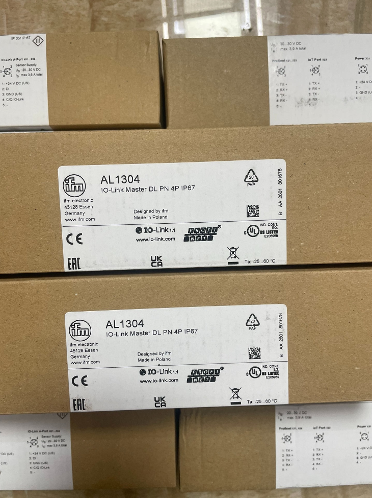

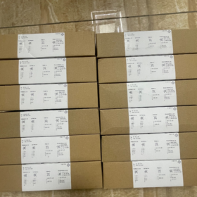
Posicionamiento básico del producto
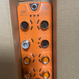
Nombre completo del modelo: AL1304 DataLine IO-Link Master DL PN 4P IP67
Marca: MFI (Alemania)
Core Profile: 4-port Class A IO-Link master with PROFINET bus + independent dual Ethernet ports for IoT JSON/MQTT. It is a field distributed I/O module with IP67 rating, allowing direct on-machine outdoor installation without control cabinets.
Desglose del código del modelo
Alabama: DataLine series field IO-Link master
13: PROFINET bus version
04: 4-channel Class A IO-Link ports
No suffix marking = Standard industrial orange IP67 housing
- Core Hardware Port Layout (8 × M12 Connectors)
Port definitions from top to bottom:
- X1: PROFINET Ethernet Port (M12 D-coded, 100 mbps) → Connect to PLC control network
- X2: Independent IoT Ethernet Port (M12 D-coded) → Isolated IT/cloud network for uploading sensor data via JSON/MQTT
- X3~X6: 4 × Class A IO-Link Ports (M12 5-pin A-coded)
Each port integrates 2DI + 1HACER, with a total of 8DI / 4DO for the unit
- X7: Entrada de energía (M12 con codificación A, 24 VCC)
- X8: Ethernet Daisy-Chain Output (M12 D-coded) → For bus daisy-chain expansion
- Especificaciones eléctricas clave
3.1 Fuente de alimentación
Voltaje de funcionamiento: 18~30 V DC (estándar 24 V industrial DC)
Max Total Power Consumption: ≤6 W
Power Connector: M12 con codificación A, with reverse polarity and short-circuit protection
3.2 IO-Link Channels (4 × Class A)
IO-Link Version: V1.1, Conformance Class C; supports IRT, MRP, CiR and S2 redundancy
Digital Inputs per Port: 2 DE (Compatible con PNP/NPN)
Alto nivel: 11~30 V DC; Nivel bajo: 0~5 V DC
Digital Output per Port: 1 HACER (PNP)
Max Load per Channel: 300 mamá, with short-circuit/overload protection
Corriente máxima por canal: 0.3 A; total output current limiting for four channels
3.3 Communication Performance
PROFINET Control Network (X1/X8)
Velocidad: 100Base-TX, 100 mbps
Supported Topologies: Line topology, MRP ring redundancy
Compatibilidad: Siemens S7-1200, S7-1500, UPC 315, UPC 400 and other PROFINET controllers
Supporting File: GSDML file available for download with official manuals
Independent IoT Ethernet (X2, Hardware-Isolated Network)
Protocolos: TCP/IP JSON, MQTT
Velocidad: 10/100 Mbps auto-negotiation
Ventaja principal: Hardware isolation between control network and IT cloud network, preventing external network intrusion into PLC control systems. Raw sensor data is uploaded directly to MES/cloud platforms without occupying PLC cycle time.
3.4 Ambiental & Especificaciones mecánicas
Clase de protección: IP67 (waterproof and dustproof, direct mounting on machine bodies)
Temperatura de funcionamiento: -25°C ~ +60 °C
Temperatura de almacenamiento: -40℃ ~ +80℃
Material de la carcasa: Polyamide PA, vibration-resistant and oil-resistant
Vibration Standards: EN 60068-2-6, EN 60068-2-27
Montaje: 2 through holes for M4 screws; wall-mounted or machine-mounted
- Core Functional Highlights
- Dual Isolated Network Architecture
PROFINET is dedicated to PLC motion and logic control; the independent IoT port separately uploads diagnostic data such as temperature, counters and vibration without mutual interference, complying with factory network security standards.
- 4 IO-Link Channels with Integrated DI/DO
Each channel can directly connect IO-Link sensors (presión, fluir, fotoeléctrico, codificadores, temperature modules) while providing built-in digital inputs and outputs, eliminating the need for extra terminal blocks.
- Complete Advanced PROFINET Features
IRT real-time synchronization, MRP ring redundancy, CiR online configuration modification, SNMP network diagnostics, suitable for high-speed production lines and robot workstations.
- Free Configuration Software moneo|configure free
Automatically scans all IO-Link devices, one-click import of IODD files, batch parameter downloading, online diagnostics and fault alarms.
- Diagnóstico Integral
Real-time upload of port short-circuit, rotura de cable, device loss, undervoltage and communication timeout signals to PLC; fault JSON logs are simultaneously pushed via the IoT port.
- Embalaje estándar & Accesorios opcionales
Standard Delivery
1 × AL1304 Main Unit
Printed Quick Installation Manual
Separately Orderable Accessories
M12 D-coded PROFINET cables (derecho / angled)
M12 A-coded power cables
Port dust protection caps
Daisy-chain Ethernet cables
- Series Selection Comparison (AL13xx PROFINET Series)
| Modelo | IO-Link Ports | IoT Port | Clase de protección | Escenarios de aplicación típicos |
| AL1304 | 4 × Class A | Independent Dual Ethernet Ports | IP67 | Small workstations, standalone machines, applications with ≤4 sensors |
| AL1306 | 8 × Class A | Independent Dual Ethernet Ports | IP67 | Multi-sensor stations, distributed data acquisition on production lines |
| AL1307 | 8 × Class A | Independent Dual Ethernet Ports | IP69K | Alimento & pharmaceutical environments with high-pressure washdown |
- Industrias de aplicación típicas
Soldadura automotriz & líneas de recubrimiento, machine tool centers
Packaging production lines, líneas de clasificación logística
moldeo por inyección, goma & equipo de plastico, small custom automation machines
Equipment cloud data upload, MES data acquisition projects
Complete Installation Manual for IFM AL1304 IO-Link Master
Información del documento
Modelo: AL1304 (DL PN 4P IP67)
Versión: Original Standard Installation & Manual de operación
Solicitud: On-site wall/machine-mounted IO-Link master with isolated PROFINET + IoT dual networks
Clase de protección: IP67, direct outdoor/machine mounting without control cabinets
Tabla de contenido
- Mandatory Safety Requirements
- Inspección previa a la instalación & Lista de herramientas
- Especificaciones de instalación mecánica (Dimensiones, Fijación, Esfuerzo de torsión, Toma de tierra)
- Definición de puerto & M12 Connector Wiring Specifications
- Step-by-Step Electrical Wiring Procedures
- Cableado & EMC Anti-Interference Specifications
- Lista de verificación de inspección previa al encendido
- Power-On LED Indicator Status Guide
- Unit Disassembly Specifications
- Prohibiciones de instalación & Fault Prevention
- List of Original Optional Accessories
1 Mandatory Safety Requirements (Must Be Followed)
⚠️ Critical Hazard Warnings
- Cut off all 24 V power before any installation, wiring removal or disassembly. Hot plugging/unplugging of M12 connectors is strictly prohibited, as it will burn port driver chips.
- The power supply is SELV/PELV safety extra-low 24 VCC; connection to 220 VAC or 380 VAC mains power is forbidden.
- The metal mounting base must be reliably earthed to prevent electrostatic discharge and surge damage to Ethernet and IO-Link channels.
- For food/washdown applications, avoid direct high-pressure water spraying onto connector roots. Select AL1307 (IP69K) for long-term washdown exposure.
- Rango de temperatura ambiente: Operating -25℃ ~ +60℃; Installation temperature ≥0℃ to avoid seal hardening and water ingress at low temperatures.
2 Inspección previa a la instalación & Lista de herramientas
2.1 Inspección de desembalaje
- Check the AL1304 unit for cracks, dents and deformed connectors; confirm FKM sealing rings are intact and undamaged.
- Standard contents: Unidad principal, printed quick installation manual. Cables and dust caps are not included and must be ordered separately.
- Verify model marking AL1304, confirmar 4 Class A IO-Link channels and dual D-coded Ethernet ports.
2.2 Herramientas necesarias
llave dinamométrica (0.5~3 N·m), M5 bolts, flat washers/spring washers
14 mm open-end wrench (for tightening M12 connectors)
Multímetro (24 V continuity and short-circuit testing)
Cable ties, cable clamps, shielded industrial Ethernet cables
3 Especificaciones de instalación mecánica
3.1 Overall Unit Dimensions
152 milímetros (h) × 59.3 milímetros (W.) × 38.4 milímetros (D)
3.2 Métodos de montaje: Muro / Machine Body Mount (No DIN Rail Clips)
- Two mounting through holes on the top and bottom rear of the unit; secure with 2 × M5 bolts + flat washers.
- Standard tightening torque: 1.8 Nuevo Méjico. Excessive torque is forbidden to avoid housing deformation and seal failure.
- Mounting Surface Requirements: Flat metal plate free of burrs and oil contamination. Max tilt angle ≤90°. Do not mount upside down with connectors facing upward (risk of water pooling ingress).
- Earthing Requirements: The two M5 mounting bolts also serve as unit earthing terminals; the metal base shall connect to protective earth PE. For non-metallic mounting plates, run a separate earthing wire to the PE busbar.
3.3 Mounting Clearance Requirements
Reserve ≥30 mm vertical clearance above and below the unit for heat dissipation; ≥20 mm side clearance to prevent heat accumulation.
Keep a minimum distance of 150 mm from inverter and servo power cables to reduce electromagnetic interference.
4 Full Unit Port Definition (8 M12 Connectors from Top to Bottom)
| Port No. | Tipo de conector | Coding | Descripción de la función |
| X1 | M12 4-pin Ethernet | D-coded | PROFINET control network (connect to PLC) |
| X2 | M12 4-pin Ethernet | D-coded | Independent isolated IoT network (MQTT/JSON cloud/MES upload) |
| X3/X4/X5/X6 | M12 5-pin IO-Link | Codificado A | 4 Class A IO-Link channels, each with integrated 2DI+1DO |
| X7 | M12 5-pin Power | Codificado A | 24 VDC power input |
| X8 | M12 4-pin Ethernet | D-coded | PROFINET daisy-chain output |
4.1 General M12 Connector Tightening Torque (Estándar de fábrica)
Hand-tight basic torque: 0.6 Nuevo Méjico
Severe vibration/oil environments: 1.2~1,5 N·m (tightened with 14 mm wrench)
Do not power on if sealing rings are missing; IP67 protection will be lost.
5 Step-by-Step Electrical Wiring Procedures
5.1 X7 Power Port (M12 A 5-pin Standard IO-Link Pinout)
Definición de PIN (viewed from plug front):
1: Marrón +24 En DC
2: Black DI1 (shared digital input for channels)
3: Azul 0 V GND
4: White DI2 (shared digital input for channels)
5: Grey PNP DO output (máximo 300 mamá)
Power supply range: 18~30 VCC, total power consumption ≤6 W. Power supply built-in reverse polarity, short-circuit and overcurrent protection.
5.2 IO-Link Ports X3~X6 (Independent 5-pin A-coded per Channel)
Each channel provides independent power supply, IO-Link communication and integrated DI/DO without external terminals:
Pin1: 24 V L+ sensor supply
Pin2: DE (PNP/NPN compatible input)
Pin3: 0 VL-
Pin4: Línea de comunicación IO-Link (C/Q)
Pin5: PNP DO output, 300 mA per channel current limiting
5.3 D-coded 4-pin Industrial Ethernet Cables for X1/X2/X8
Pin1: TD+ Transmit +
Pin2: TDTransmit –
Pin3: RD+ Receive +
Pin4: RDReceive –
Shield layers shall be earthed at both ends to suppress motor interference. X2 IoT network and X1 control network are hardware-isolated with no intercommunication.
6 Cableado & EMC Anti-Interference Specifications
- Separate power cables (servo, inversor) and IO-Link/Ethernet cables into different cable trays with a minimum spacing of 150 milímetros. Use metal shielded trays for separation if routing together is unavoidable.
- Minimum bending radius of M12 cables ≥ 5 × cable outer diameter; sharp bending and squeezing at connector roots are prohibited.
- Cable Length Limits:
IO-Link cable: ≤20 m
PROFINET industrial Ethernet cable: ≤100 m (100 mbps)
- All unused spare ports must be fitted with original dust and waterproof caps, otherwise IP rating will be invalidated.
- The shield of all shielded Ethernet cables shall be 360° crimped onto the metal connector shell with single-point earthing.
7 Mandatory Full Pre-Power-On Inspection Checklist
- Fijación Mecánica: Two M5 bolts tightened to 1.8 Nuevo Méjico; unit fixed without wobble.
- Earthing Test: Multimeter to verify continuity between mounting base and PE protective earth; earthing resistance <4 Ω.
- Cable Tightness: All M12 connectors tightened to 0.6~1.5 N·m with no looseness.
- Short-Circuit Test: Desconecte la fuente de alimentación, use multimeter to confirm no short-circuit between X7 Pin1 and Pin3, and no short-circuit to ground on Pin1/Pin3 of all IO-Link channels.
- Network Segregation: X1 connected to PLC control network, X2 to independent IT/MES network; connecting both ports to the same switch is forbidden.
- All spare ports fitted with dust caps.
8 Power-On LED Indicator Status Guide
Status LEDs integrated on the front panel for rapid fault diagnosis after power-up:
- PWR Power LED (Solid Green): Fuente de alimentación normal; Off = No power / Cortocircuito; Flashing = Undervoltage <18 V
- NET1 (X1 PROFINET):
Solid On: Link established; Brillante: Intercambio de datos; Apagado: Cable break / No connected device
- NET2 (X2 IoT Network):
Solid On: Stable IT network link; Brillante: MQTT/JSON data uploading
- CH1~CH4 Channel LEDs (X3~X6):
Solid Green: Normal IO-Link device communication
Flashing Red: Port short-circuit, cable breakage or device loss
Apagado: No device connected to the channel
9 Unit Disassembly Specifications
- First cut off the 24 V main power supply and wait 30 seconds for discharge.
- Loosen all M12 connectors with a 14 mm wrench; do not pull cables forcibly.
- Loosen the two rear M5 mounting bolts and remove the unit.
- Install port dust caps immediately after disassembly to protect sealing rings.
10 Prohibiciones de instalación & Fault Prevention
❌ Forbidden: Mount unit upside down with connectors facing downward (water pooling into sockets)
❌ Forbidden: Tighten fixing bolts above 1.8 Nuevo Méjico; housing cracking and water leakage will occur
❌ Forbidden: Hot plug/unplug M12 connectors; communication chips will burn out
❌ Forbidden: Parallel close routing of power cables and IO cables, causing communication packet loss
❌ Forbidden: Connect X1 and X2 ports to the same switch, breaking network isolation security
❌ Forbidden: Long-term outdoor operation without dust caps; dust will cause port short-circuits
Common Installation Fault Prevention:
- Frequent communication disconnections: Check connector torque, shield earthing and separation distance from power cables
- Persistent port short-circuit alarms: Verify IO-Link sensor wiring and ensure load ≤300 mA
- PROFINET device not detected: Check GSDML file, dirección IP, device name and D-coded Ethernet cable
- Failed IoT data upload: X2 uses an independent network segment with no IP conflict with the PLC network
11 Original Optional Accessories (Ordenado por separado)
- M12 D-coded straight/angled PROFINET Ethernet cables (2 metro / 5 metro / 10 metro)
- M12 A-coded 5-pin power cables
- Standard 4/5-core IO-Link sensor cables
- Polvo & waterproof port caps (single-channel / full set for unit)
- Stainless steel mounting brackets (for high-vibration equipment)
Notas de traducción
- Industrial automation professional terms adopt international standard industry expressions (Enlace IO, PROFINET, PNP/DI/DO, MRP, TRI, CiR, MQTT, JSON, SELV/PELV, CEM, GSDML, IODD, Carril DIN, PE earth etc.)
- Esfuerzo de torsión, temperatura, longitud, current units retain international metric symbols consistent with IFM official English datasheets
- M12 connector coding (Codificado A / D-coded), pinout labels and protection class IP67/IP69K follow original factory standard terminology
- Tables, warning symbols, prohibited marks and document structure fully match the original Chinese text layout for direct use in overseas technical manuals





NH42-63-318x560.png "Interruptores de transferencia automática tipo PC CHINT (ATS)NH42-63/4SZ")



