 contactor,cortacircuitos,sensor,Codificador,SOCIEDAD ANÓNIMA,Convertidor

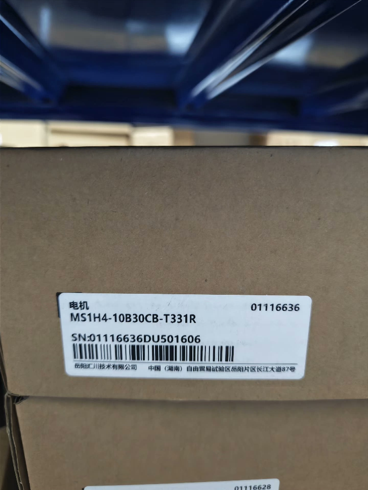

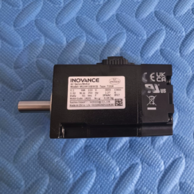
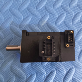
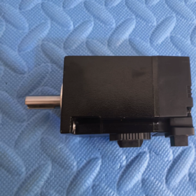
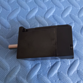
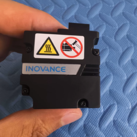
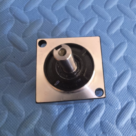
MS1H4-10B30CB-T331R
| Segmento | Definición |
| MS1 | Serie MS1 generales servomotor |
| H4 | Inercia media, Pequeña capacidad |
| 10B | Clasificación de potencia: 10×10 = 100W (0.1kilovatios) |
| 30do | Velocidad nominal: 30×100 = 3000 rpm |
| B | Clase de voltaje: Monofásico/Trifásico AC220V |
| T3 | 18-bit Multivuelta Absoluta Codificador |
| 3 | Configuración del eje: Con chavetero + Rosca interna en el extremo del eje |
| 1 | Accesorio: Con sello de aceite, Sin freno de parada electromagnético |
| R | Versión de brida estándar |
Nota de distinción: A3 = codificador absoluto multivuelta de 23 bits; T3 = codificador absoluto multivuelta de 18 bits. Los cables son mecánicamente intercambiables., pero la resolución difiere; Los parámetros no deben usarse sin reconfiguración..
- Principales especificaciones eléctricas
| Artículo | Valor |
| Potencia nominal | 100W. / 0.1kilovatios |
| Par nominal | 0.32 Nuevo Méjico |
| Par máximo | 1.12 Nuevo Méjico (350% Sobrecarga) |
| Velocidad nominal | 3000 rpm |
| Velocidad máxima | 7000 rpm |
| Corriente nominal | 1.27 A |
| Corriente máxima | 4.78 A |
| Momento de inercia del rotor | 0.072 ×10⁻⁴ kg·m² |
| Tamaño de brida del marco | 40 milímetros |
| Codificador | 18bit Codificador absoluto multivuelta |
| Freno de mantenimiento | No equipado |
| Clase de protección | IP67 (Excluyendo el área del sello del eje) |
| Tipo de servicio | Operación continua S1 |
- Servovariadores compatibles
✅ Partidos recomendados:
Serie SV660PS (Corriente principal)
Serie SV670PS
No es directamente compatible con unidades IS620 heredadas. El cable adaptador del codificador es obligatorio si se utiliza IS620.
- Aplicaciones típicas
Pequeño equipo de posicionamiento, 3equipo de automatización c, mecanismos de transporte en miniatura, plataformas de ajuste, módulos lineales, máquinas dispensadoras, diapositivas de inspección, pequeñas unidades de indexación.
- Comparación de modelos derivados (Para adquisiciones & Reemplazo)
MS1H4-10B30CB-A331R: 23-codificador absoluto multivuelta de bits (Versión de alta precisión)
MS1H4-10B30CB-T32R: Con freno de parada y retén de aceite.
MS1H4-10B30CB-T30R: Sin retén de aceite y freno de parada
- Selección & Precauciones de reemplazo
- Este modelo no tiene freno de parada.. No lo utilice para cargas de eje vertical.; seleccione la variante equipada con freno T32R para aplicaciones verticales.
- T3 (18-poco) y A3 (23-poco) Los codificadores comparten interfaces de conector idénticas.. El tipo de codificador debe reconfigurarse en los parámetros del variador después del reemplazo del motor..
- Velocidad máxima 7000 rpm; Se recomienda una velocidad de funcionamiento sostenida ≤6000 rpm para evitar un aumento excesivo de temperatura..
- Diseño de eje: chavetero + rosca interna del extremo del eje. Verifique las dimensiones del acoplamiento durante el reemplazo.
INNOVACIÓN MS1H4-10B30CB-T331R (40 Marco, 100W., Sin freno) Dimensiones del contorno
Unidad: milímetros, Este modelo = Versión sin freno; Las dimensiones dentro de los corchetes representan la longitud total de la variante equipada con frenos T32R..
- Dimensiones generales de montaje
| Marca | Descripción | Valor | Tolerancia |
| LC | Ancho de la base de montaje con brida cuadrada | 40 | Estándar 40 Marco |
| LA | Diámetro exterior de la brida | 46 | — |
| LL | Longitud total del motor (Superficie de brida al extremo trasero) | 91 | Versión con freno: 121.5 |
| LR | Longitud del saliente del eje (Cara de la brida al extremo del eje) | 25 | ±0,3 |
| libra | Diámetro del eje de salida | Φ30 h7 | 0/-0.021 |
| LG | Profundidad del chavetero | 5 | — |
| EL | Ancho del chavetero | 2.5 | ±0,5 |
| LJ | Chaflán del extremo del eje | 0.5 | ±0,35 |
| LZ | Montaje a través del orificio | 2×Φ4.5 | Dispuestos en diagonal |
| LH | Distancia al centro del orificio de montaje | 34.3 | — |
- Detalles del eje de salida (chavetero + Rosca interna del eje, Sufijo “3” Especificación del eje)
- Diámetro del eje: Φ30h7
- Tamaño de clave paralela: Ancho 2,5 mm, Profundidad 5mm
- Extremo del eje: Orificio roscado interno (para acoplamiento anillo de retención/posicionamiento)
- Longitud de extensión del eje: 25milímetros
- Cargas permitidas en el eje
Carga radial permitida: 120 norte (en el extremo del eje)
Carga axial permitida: 40 norte
⚠️ La sobrecarga acelerará el desgaste de los rodamientos y acortará la vida útil.
- Peso
MS1H4-10B30CB-T331R (Sin freno): 0.75 kilos
Derivado T32R (Con freno): 0.98 kilos
- Notas clave de montaje
- Clase de protección IP67: La región del sello de aceite del eje y los conectores eléctricos están excluidos de la clasificación IP67.. Evite la inmersión permanente en agua..
- Montaje: Montaje de brida frontal; sujetador recomendado M4, par de apriete 1,2~1,5 N·m
- Conectores: Los conectores de alimentación y codificador están dispuestos lateralmente en la parte trasera del motor.. Autorización de reserva en el diseño de equipos..
- Advertencia de intercambio mecánico: Variante equipada con freno T32R longitud total 121,5 mm; No se puede intercambiar directamente sin modificar el marco mecánico..
- Números de pieza de cables coincidentes (Adquisición de repuestos)
Cable de alimentación: T6-L-M04-xxx (40-cable de alimentación del marco)
Cable de codificador para absoluto multivuelta de 18 bits: T6-E-T3-xxx
No es directamente compatible con cables definidos para codificador A3.
INNOVACIÓN MS1H4-10B30CB-T331R (40 Marco, 100W., Sin freno) Especificación de instalación completa
- Tipo de montaje básico
Montaje estándar: Montaje de brida frontal (Brida IEC B3)
Solo se admite el montaje con brida; sin estructura de montaje en pies. Dimensión de brida cuadrada 40 mm.
Sufijo R = Versión con brida estándar; Eje macizo con chaveta y rosca interior en el extremo del eje.
- Especificación de sujetadores (Crítico)
- Orificios de montaje: 2 Orificios pasantes Φ4,5 distribuidos diagonalmente
- Perno recomendado: Tornillo de cabeza hueca hexagonal M4 (Grado ≥8,8)
- Par de apriete estándar: 2.4 Nuevo Méjico
✅ Regla de operación: Apriete diagonalmente en varias pasadas. Evite el apriete total unilateral para evitar la distorsión de la brida.
- Plano de referencia de montaje: Superficie de la brida delantera del motor; planitud ≤0.02mm.
- Orientaciones de montaje permitidas
| Orientación de montaje | Permisibilidad | Requisitos obligatorios |
| Montaje horizontal (eje horizontal) | ✅ Recomendado | Disipación óptima del calor; sin restricciones adicionales |
| Eje de montaje vertical hacia abajo (Carga colgando hacia abajo) | ✅ Permitido | Espacio libre de reserva para conectores de cables; Sin freno de retención: NO suspenda las cargas cuando la energía esté apagada. |
| Eje de montaje vertical hacia arriba (Cargar hacia arriba) | ⚠️ No recomendado para operación a largo plazo | Envejecimiento acelerado del sello de aceite delantero; Sólo aplicable para equipos de ciclo corto.. |
| Montaje inclinado (Cualquier ángulo) | ✅ Permitido | Coloque los conectores hacia abajo para evitar la entrada de agua condensada.. |
Advertencia importante: No hay freno de parada electromagnético instalado. Estrictamente prohibido para cargas de elevación vertical.. Seleccione el modelo T32R equipado con frenos para ejes verticales!
- Especificación de conexión del eje del motor a la carga
4.1 Resumen de parámetros del eje
Diámetro del eje Φ30 h7; extensión del eje 25mm; ancho de llave paralela 2,5 mm; rosca interna en el extremo del eje.
4.2 Regla de instalación del acoplamiento
❌ Nunca golpee el extremo del eje del motor directamente con un martillo.!
El impacto dañará el anillo magnético del codificador y desactivará permanentemente el motor..
✅ Práctica correcta: Utilice herramientas de montaje hidráulicas., montaje termico (temperatura ≤80 ℃), o método de gato de tornillo para acoplar a presión.
4.3 Tolerancia a la coaxialidad
Desplazamiento radial máximo permitido: ≤0,03mm
Desalineación angular máxima: ≤0,5°
Acoplamiento recomendado: Acoplamiento flexible de mandíbula / Acoplamiento de diafragma
La desalineación excesiva causa vibración, Desgaste prematuro de los rodamientos y ruido a alta velocidad..
4.4 Carga externa continua permitida
Carga radial permitida en el extremo del eje: 120 norte
Carga axial permitida en el extremo del eje: 40 norte
La transmisión por correa y por engranajes generan fuerzas radiales continuas; El cálculo de la carga es obligatorio para evitar exceder los límites..
- Disipación de calor & Espacio libre de instalación
- Método de enfriamiento: Enfriamiento por convección natural. Reserve ≥30 mm de espacio libre alrededor de las aletas de refrigeración.
- No fije el extremo trasero del motor directamente a una hoja de metal o a una cubierta cerrada..
- Reduce la potencia del motor cuando la temperatura ambiente excede continuamente los 40°C; reducir la potencia para la altitud >1000metro.
- Temperatura máxima permitida de la superficie de la carcasa durante el funcionamiento: ≤120°C.
- Conector & Reglas de enrutamiento de cables
- Los conectores de alimentación y codificador están ubicados en el costado de la parte trasera del motor.. Reservar espacio de movimiento de cables en diseño mecánico..
- Alivio de tensión del cable: Instale la abrazadera del cable junto a los conectores para evitar la tensión causada por el peso del cable que tira de los conectores..
- Separación de cableado: Cables de alimentación separados y cables de codificador blindados; mantener una distancia paralela de ≥30 cm. Cables cruzados a 90° siempre que sea posible.
- Resistente al agua para conectores: Asegúrese de que los enchufes estén completamente bloqueados. Evite conectores orientados hacia arriba dentro del equipo para evitar la acumulación de agua.. La clasificación IP67 se aplica solo a la carcasa del motor.; Los conectores no están sellados IP67..
- Especificación de puesta a tierra
- Conecte de forma fiable el terminal PE de la carcasa del motor a la tierra de protección.
- Las capas de blindaje del cable de alimentación y del cable del codificador deben estar conectadas a tierra en ambos extremos a la barra colectora de tierra del gabinete según el estándar Inovance..
- Resistencia a tierra <100Ω para evitar la desviación de la posición del codificador y fallas de comunicación causadas por interferencias electromagnéticas.
- Prohibiciones de instalación (Reglas obligatorias)
- Está prohibido soldar o soldar por puntos en la carcasa del motor.; La alta temperatura destruirá el codificador interno..
- Está prohibido rectificar o mecanizar la brida y el eje del motor..
- Evite la operación prolongada de parada del motor.
- Evite el lavado continuo del sello de aceite del eje con fluido de corte o contaminación por aceite..
- No levante/mueva el motor por cables o conectores durante su manipulación.; Sujete sólo la carcasa de la brida..
- Procedimiento de instalación estándar
- Base de montaje limpia, eliminar rebabas y virutas de metal.
- Fije la brida del motor a la superficie de montaje, Inserte los pernos M4 y aplique un preapriete diagonal..
- Asegure el motor temporalmente y ensamble el acoplamiento..
- Ajuste la posición del motor y verifique la coaxialidad con el indicador de cuadrante.
- Apriete los pernos al par especificado de 2.4 N·m en secuencia diagonal.
- Instalar soportes para cables, Conecte el cable de alimentación y el cable del codificador..
- Compruebe si hay interferencias mecánicas y riesgos de tensión del cable antes de la puesta en servicio..





NH42-63-318x560.png "Interruptores de transferencia automática tipo PC CHINT (ATS)NH42-63/4SZ")



