 contactor,cortacircuitos,sensor,Codificador,SOCIEDAD ANÓNIMA,Convertidor

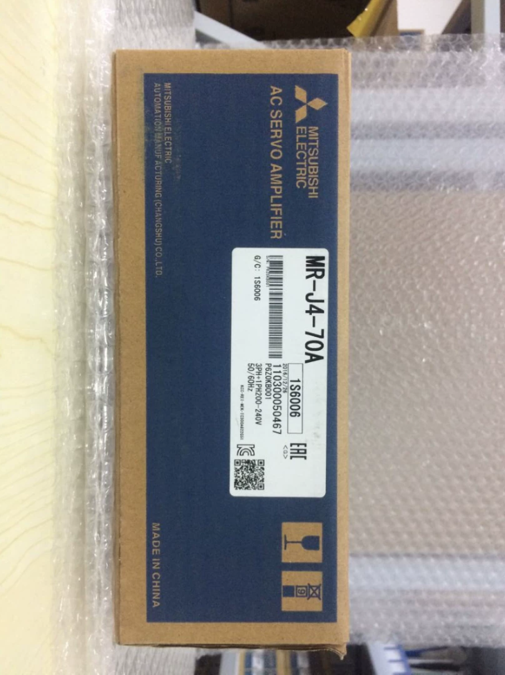

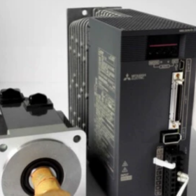
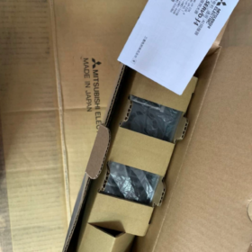
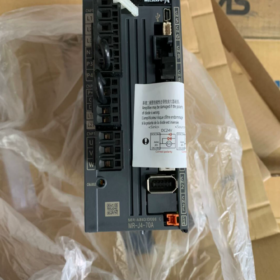
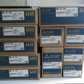
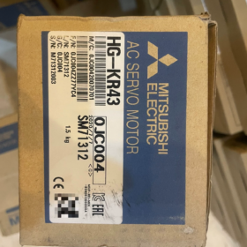
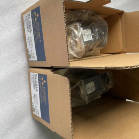
(Serie MELSERVO-J4, 3.5 kilovatios)
Señor-J4: 4th-generation high-performance servoamplificador of J4 series
350: Rated power 3.5 kW
A: Legumbres + analog general-purpose interface (hard-wired command, no SSCNET optical fibre bus). Bus version: Señor-J4-350B. Suffix -RJ: Supports external linear encoder for full closed-loop control.
⚠️ Models of 3.5 kW and higher only accept 3-phase AC200-240V main power supply. Single-phase supply is NOT allowed.
Especificaciones eléctricas básicas
| Artículo | Parámetro |
| Main circuit input | 3‑phase AC200‑240V, 50/60Hz; rango permitido:170‑264V |
| Corriente de entrada nominal | 21.7A |
| Corriente de salida nominal | 20A |
| Corriente de salida máxima | 60A (3‑fold, max.10s short‑time) |
| Controlar la fuente de alimentación | DC24V±10%, 0.5A (including STO safety circuit) |
| Speed loop bandwidth | 2.5 kilociclos |
| Resistencia regenerativa incorporada | 850W.; external regenerative resistor required for vertical loads or frequent start‑stop cycles |
| Función de seguridad | STO (Desconexión de par segura), compliant with IEC61800‑5‑2 |
| Pulse command | Diferencial:4Mpps; Open‑collector:200kpps |
| Analog command | ±10V (velocidad / referencia de par) |
| Encoder resolution | motor emparejado: 22-poco (4194304 p/r) |
| Dimensiones generales | 140×180×195 mm |
| Peso | 2.8 kilos |
| Clase de protección | IP20, solo para instalación en gabinete |
Compatible Servo Motors (200Clase V)
Inercia media: HG-SR352, HG-SR353; Con freno: HG-SR352B, HG-SR353B
Baja inercia: HG-KR353, HG-KR353B (con freno)
J2S / JE series motors cannot be used directly due to encoder protocol incompatibility.
Descripción general de la interfaz
- CN1: I/O signal terminal block, pulse/direction, Entrada analógica de ±10 V, digital DI/DO, STO safety circuit
- CN2: Motor encoder connector
- CN3: USB service port, for PC connection with MR-Configurator2 for commissioning, monitoring and parameter backup
- CN4: Full-closed-loop linear encoder interface (activated for -RJ variant only)
- Terminales del circuito principal: L1/L2/L3 main power; U/V/W to motor; B1-B2 for external regenerative resistor.
Características principales
Three switchable control modes: Posición, Velocidad, Esfuerzo de torsión. Compatible with pulse-output PLC (FX/Q/L/R series) and 3rd-party pulse motion controllers.
Advanced Vibration Suppression Ⅱ, adaptive filter, auto-tuning, ToughDrive instantaneous power failure protection, quadrant protrusion compensation, machine diagnosis function.
A/B/Z phase encoder pulse output, 2-channel analog monitor output.
Drop-in replacement for MR-J3-350A (mechanical mounting compatible; parameters require re-tuning).
Referencia de selección alternativa
- Same series bus version: Señor-J4-350B (SSCNET Ⅲ/H optical fibre bus, for multi-axis synchronous systems)
- New-generation upgrade: Señor-J5-350A (mayor ancho de banda; hardware mounting not fully compatible, wiring and motor compatibility to be verified).
- Retrofit for legacy equipment: Upgrade MR-J3-350A to this unit; pay attention to regenerative resistor and parameter migration.
Lista de verificación de inspección de unidades de segunda mano
- control visual: Burnt marks, scorched terminals, condensadores abultados.
- Prueba de aislamiento: Megger test between main-circuit U/V/W and protective earth.
- Encendido sin motor: comprobar si hay alarmas; verify STO circuit status.
- No-load motor jog test: Check abnormal noise, vibration and encoder feedback.
- Use MR-Configurator2 to read internal alarm history.
Alarmas comunes
AL.30: Regenerative error. Check regenerative resistor sizing. External resistor is mandatory for frequent start-stop or vertical axis applications.
AL.16: Encoder communication error. Inspect CN2 cable and connectors.
AL.E6: STO circuit open. CN1 STO terminals not short-circuited or external safety signal triggered.
Supplementary Notes for MR-J4-350A (Sección 2)
- Typical Pulse-Direction Wiring for Position Control
CN1 terminals, differential signalling (recommended for high noise immunity, for PLC differential output)
- Pulse command: PP ← PLC pulse output; NP ← pulse negative
- Direction command: PD ← PLC direction output; ND ← direction negative
- STO safety circuit: Short-circuit STO1-STO2 and STO3-STO4 on CN1, otherwise AL.E6 occurs and servo cannot run.
- DC24V control supply: DICOM to 24V+; DOCOM to 24V-.
Parameter Settings for Pulse-Direction Mode
| Número de parámetro. | Configuración | Descripción |
| Pr.000 | 0 | Position control mode |
| Pr.001 | 1 | Legumbres + direction input mode |
| Pr.042 | 10000 | Electronic gear numerator, adjust as‑required |
Open-collector Mode (Legacy PLC, not recommended for long cable runs)
máx.. pulse frequency limited to 200 kpps; cable length ≤3 m, susceptible a interferencias electromagnéticas.
Precauciones de cableado
- L1/L2/L3 must be fed with 3-phase 200-240V AC. Never apply single-phase 220V to MR-J4-350A, power-supply fault alarm will trigger.
- Incorrect U/V-W phase sequence causes shaking and AL.37 alarm.
- Usar mitsubishi shielded servo cable for CN2 encoder wiring; shield grounding at both ends.
Software de puesta en marcha
MR-Configurator2. Connect PC USB to CN3 for jog operation, auto-tuning, alarm history reading and parameter backup.
Full Differences & Guía de reemplazo: MR-J4-350A replacing MR-J3-350A
Unidad original: Señor-J3-350A; Replacement unit: Señor-J4-350A; Both 3.5 kW, 200clase V.
- Instalación Mecánica & Hardware
- Mounting cut-out fully compatible: Screw hole positions match, direct retrofit without cabinet modification.
- Overall dimensions nearly identical; heat-sink layout differs without impact on fitting.
- Main-circuit terminals L1/L2/L3, UV/V/W, B1-B2 for regenerative resistor: pin-to-pin identical. Existing power cables and external regenerative resistor can be reused.
- ✅Major difference: CN1 control I/O connector
Señor-J3-350A: Spring-clamp terminal block
Señor-J4-350A: Removable plug-in connector
Field retrofit note: Existing MR-J3 CN1 harness cannot plug directly into MR-J4. Two options:
① Purchase dedicated CN1 plug for MR-J4 and re-terminate existing wires.
② Keep old J3 terminal block and implement external flying-wire adapter.
- CN2 encoder connector: Same physical plug, protocolo diferente
MR-J4-350A can drive legacy MR-J3 HF-SP352 motor (firmware version A8 or above).
MR-J3 cannot drive J4-series HG-SR motors.
Physical encoder cable plug fits, double-check for vertical axes; use genuine shielded cables.
- Nuevo puerto de servicio USB CN3 (ausente en MR-J3). Utilice MR-Configurator2 para la configuración.
- STO safety circuit (Causa raíz de AL.E6)
MR-J3 no tiene función de seguridad STO incorporada.
Los terminales STO MR-J4 están abiertos de fábrica. Short-circuit STO1-STO2 and STO3-STO4 on CN1, de lo contrario, AL.E6 aparece inmediatamente después del encendido. Este es el problema de campo más frecuente durante el reemplazo..
- Comparación de resistencias regenerativas
| Artículo | MR‑J3‑350A | MR‑J4‑350A |
| Potencia permitida de la resistencia regenerativa incorporada | 300W. | 850W. |
| Definición del terminal B1‑B2 | Idéntico | Idéntico |
La resistencia regenerativa externa existente puede permanecer en servicio. Para cargas frecuentes de arranque-parada o de eje vertical, No confíe únicamente en la resistencia interna.; mantenga la resistencia externa conectada.
- Compatibilidad de motores
- ✅MR-J4-350A es compatible con HF-SP352 heredado / Motores HF-SP352B de la plataforma J3, firmware ≥A8 requerido.
- ❌MR-J3-350A no puede accionar motores HG-SR352 de la serie J4.
- Cables de alimentación de motores: mechanically interchangeable for reuse. Encoder cables share identical plug but differ in protocol; legacy HF-motor cables are acceptable.
- Parameter Migration (Do NOT import MR-J3 parameter files directly)
MR-J3 parameter files cannot be loaded into MR-J4. Partial parameter numbers have changed; enter values manually, do not copy all parameters wholesale.
Key Parameter Mapping (Pulse-Direction Position Mode)
| Función | MR‑J3 Parameter No. | MR‑J4 Parameter No. | Observaciones |
| Control mode selection | Pr.0 | Pr.000 | Position mode =0 |
| Pulse input mode (Pulso+Dirección) | Pr.1 | Pr.001 | Pulse+Direction =1 |
| Electronic gear numerator | Pr.42 | Pr.042 | Electronic gear ratio must be re‑verified |
| Electronic gear denominator | Pr.43 | Pr.043 | |
| máx.. command pulse frequency | Pr.21 | Pr.021 | MR‑J4 differential input up to 4Mpps vs. MR‑J3 max.1Mpps |
MR-J4 accepts higher pulse frequency (4Mpps differential, MR-J3 only 1Mpps). Higher pulse rates from PLC are achievable after replacement.
Tuning Remarks
MR-J4 implements Advanced Vibration Suppression Ⅱ and adaptive filter gains. Do not copy gain values directly from MR-J3. Run auto-tune after replacement and fine-tune gains.
- Step-by-Step Power-on Retrofit Procedure
- Power off equipment; remove MR-J3-350A and mount MR-J4-350A in-situ.
- Retain existing wiring for main-circuit L1/L2/L3, U/V/W and B1-B2 regenerative resistor.
- Process CN1: Fit dedicated MR-J4 plug; short-circuit STO1-STO2 and STO3-STO4 to prevent AL.E6.
- Connect CN2 encoder cable. For legacy HF-SP motors, confirm drive firmware ≥A8.
- Encendido; perform factory reset first, then manually input critical parameters (modo, pulse-input format, electronic gear ratio).
- No-load jog test to verify rotation direction. Reverse direction by modifying bit setting inside Pr.000 (software reversal), do not swap U/V/W power phases.
- Execute auto-tune. Run machine under load; monitor for vibration or noise. Watch regenerative load factor to avoid AL.30 regenerative error.
- Typical Replacement-related Faults
- AL.E6: STO circuit not short-circuited. MR-J3 lacks STO, this fault is highly common in retrofits.
- AL.16 Encoder error: Legacy J3 motor used with outdated drive firmware → upgrade firmware.
- Poor positioning accuracy / vibración: Do not reuse J3 gain settings; perform new auto-tuning.
- AL.30 Regenerative error: Arranques y paradas frecuentes / vertical axis → inspect external regenerative resistor.
- No response to pulse command: Double-check Pr.001 pulse-input-mode setting.
- PLC Program Considerations
Power-up initialization duration differs between MR-J3 and MR-J4. For vertical-axis machines, add a short delay in PLC logic after servo-ready signal to prevent axis dropping.





NH42-63-318x560.png "Interruptores de transferencia automática tipo PC CHINT (ATS)NH42-63/4SZ")



