 contactor,cortacircuitos,sensor,Codificador,SOCIEDAD ANÓNIMA,Convertidor

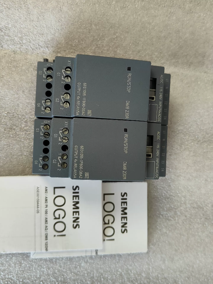

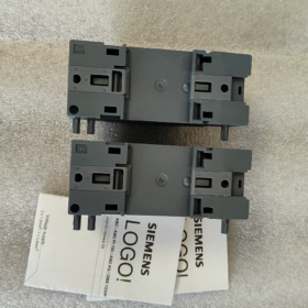
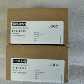
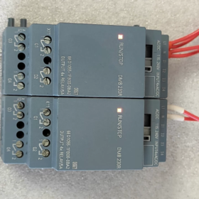
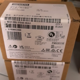
Nombre completo: LOGO! DM8 230R Digital I/O Módulo de expansión (LOGO! 8 Serie)
- Interpretación del código modelo
6ED1055-1FB00-0BA2
6ED1055: Prefix for LOGO! 8 series expansion modules
1FB: DM8 230R, 115/230 V AC/DC power supply, 4DI/4DO relay output
00: Versión de hardware
0BA2: Firmware version (LOGO!8 plataforma, incompatible with LOGO!6/7 (0BA6/0BA7) main units)
- Especificaciones eléctricas básicas
| Artículo | Especificación |
| Fuente de alimentación | 115~230 V AC/DC (85~265 V AC; 100~253 V DC) |
| Entrada digital DI | 4 canales, universal AC/DC signal |
| Lógica 0: <40 V AC /<30 V DC | |
| Lógica 1: >79 V AC />79 V DC | |
| Input delay: 0→1=40 ms; 1→0=75 ms | |
| Digital Output DO | 4 channels relay normally-open isolated contacts |
| Carga resistiva: 5 A / 250 V y | |
| Inductive load: 3 A / 250 V y | |
| Minimum load current: 100 mamá | |
| Frecuencia de conmutación máxima: 2 Hz (resistador); 0.5 Hz (inductive) | |
| Montaje | 35 carril DIN mm, ancho 2 EL (35.5 milímetros) |
| Dimensiones generales | W35.5 × H90 × D58 mm |
| Clase de protección | IP20 (solo para instalación en gabinete) |
| Temperatura ambiente de funcionamiento | -20 ℃ ~ +55 ℃, sin condensación |
| Peso | Aprox.. 0.17 kilos |
- Compatibility Instructions
✅ Supported Main Units: LOGO! 8 / 8.2 / 8.3 (0BA8 and later firmware)
Typical main unit models: 6ED1052-1FB08-0BA0, 6ED1052-1FB08-0BA1 and other 230 V main units
❌ Not Supported: LOGO! 6, LOGO!7 (0BA6/0BA7) main units. Backplane bus protocol differs, communication not available
- Definición de terminal (Arriba: Fuerza & Aporte; Abajo: Producción)
Upper Terminals (Fuente de alimentación + Aporte)
L1, norte: Module operating power supply
I1, I2, I3, I4: 4 entradas digitales
Lower Terminals (Salida de relé)
Q1, Q2, Q3, Q4: 4 independent relay normally-open contact groups (2 terminals per channel, no common terminal)
⚠️ Importante: Four relays are electrically isolated; different voltage circuits can be connected to each channel independently
- Escenarios de aplicación típicos
Small HVAC control, bomba de agua & control del ventilador, circuitos de iluminación, door interlock, simple conveyor lines. Ideal for sites equipped with existing 220 V AC sensors and contactor circuits without additional DC power supply.
- Directrices de selección & Errores comunes
- Input signal must exceed 79 V to be reliably recognized as logic 1; low voltage signals cannot be used.
- Relay mechanical contacts not suitable for high-frequency switching. Select transistor output modules for frequent operation.
- Maximum expansion limit: A single LOGO! main unit can connect up to 4 módulos de expansión.
- All input channels are recommended to use the same phase power. Do not connect I1~I4 across different phases to avoid false triggering caused by induced voltage.
- Install RC snubbers or freewheeling diodes in parallel with inductive loads (contactores, válvulas solenoides) to extend relay service life.
- Comparison with Similar Series Models
6ED1055-1FB10-0BA2 (DM16 230R): 8DI+8DO relay version with doubled I/O capacity
6ED1055-1HB00-0BA2 (DM8 24R): 24 V DC powered version
Complete Technical Documentation for siemens 6ED1055-1FB00-0BA2 (LOGO! DM8 230R)
- Información básica del producto
Nro. de orden: 6ED1055-1FB00-0BA2
Nombre del producto: LOGO! DM8 230R Digital Expansion Module (LOGO!8 Serie)
Función: 4DE / 4DO relay output expansion module
Posicionamiento: Extend I/O capacity for LOGO!8/8.2/8.3 main units, cannot run standalone
- Full Model Code Interpretation
6ED1055 1FB00 0BA2
- 6ED1055: LOGO! 8 series expansion module category
- 1FB: DM8 230R, 115~230 V AC/DC power supply, 4-channel AC input, 4 independent normally-open relay outputs
- 00: Revisión de hardware
- 0BA2: Firmware version (LOGO!8 plataforma, incompatible with LOGO!6/7 (0BA6/0BA7) controladores)
- Detailed Electrical Specifications
3.1 Fuente de alimentación
| Parámetro | Especificación |
| Tensión nominal | 115…230 V AC/DC |
| Operating Range | C.A.: 85~265 V; corriente continua: 100~253 V |
| Rango de frecuencia | 47~63 Hz |
| Module Power Consumption | máx.. 2.2 Virginia |
3.2 Entrada digital DI (I1, I2, I3, I4)
Cantidad: 4-channel universal AC/DC input
Lógica 0: <40 V AC / <30 V DC
Lógica 1: >79 V AC / >79 V DC
Input response delay: 0→1: 40 EM; 1→0: 75 EM
Tipo de entrada: Passive AC voltage input, 24 V DC signals are not allowed
Maximum cable length: 100 metro (unshielded cable)
3.3 Relay Output DO (Q1~Q4, isolated normally-open contacts)
⚠️ Four relays are mutually isolated; different voltage circuits can be wired to each channel
|Tipo de carga|Calificación de contacto|
| —| —|
|Carga resistiva (Resistors, Iluminación)|5 A / 250 V y|
|Carga inductiva (Contactores, Válvulas solenoides)|3 A / 250 V y|
|Minimum Carry Current|100 mamá (Poor contact performance may occur below this value)|
|Frecuencia de conmutación máxima|Carga resistiva: 2 Hz; Inductive load: 0.5 Hz; Mechanical no-load limit:10 Hz|
|Operación prohibida|Parallel connection of multiple output contacts for current boosting is forbidden|
- Mecánico & Parámetros ambientales
Montaje: 35 carril DIN estándar mm
Ancho: 2 EL (35.5 milímetros)
Dimensiones generales: W35.5 × H90 × D58 mm
Peso: Aprox.. 170 gramo
Clase de protección: IP20 (indoor cabinet use only)
Temperatura de funcionamiento: -20 ℃ ~ +55 ℃ (Prohibida la condensación.)
Almacenamiento & Temperatura de transporte: -40 ℃ ~ +70 ℃
Humedad relativa: 5% ~ 95%, sin condensación
Resistencia a las vibraciones: Cumple con IEC 60068-2-6
- Definición de terminal
Upper Terminals (Fuente de alimentación + Aporte)
L1, norte: Module operating power supply 115~230 V AC/DC
I1, I2, I3, I4: 4 entradas digitales
Lower Terminals (Salida de relé)
Q1 two terminals: 1st relay normally-open contact
Q2 two terminals: 2nd relay normally-open contact
Q3 two terminals: 3rd relay normally-open contact
Q4 two terminals: 4th relay normally-open contact
- System Compatibility Rules
✅ Supported Main Units (LOGO!8 Plataforma)
6ED1052-1FB08-0BA0, 6ED1052-1FB08-0BA1, all LOGO!8.2 / 8.3 230 V controllers
Maximum expansion quantity: Arriba a 4 expansion modules per LOGO! unidad principal
❌ Incompatible Equipment
LOGO!6 (0BA6), LOGO!7 (0BA7) legacy controllers. Backplane communication protocol mismatch, cannot be recognized.
- Software Configuration Requirements
Software de programación: LOGO! Soft Comfort V8.0 or higher
- Select corresponding expansion module model in project hardware catalog;
- I/O addresses of expansion modules automatically follow main unit addresses, no manual assignment required;
- Verify hardware list before program download to avoid errors caused by version mismatch.
- Certificaciones
CE, UL, CSA, CCC; Cumple con EN 61010-1, EN 55011 (EMC Class B, applicable for commercial building environments)
- Engineering Implementation Guidelines (Official Specifications)
- RC snubbers must be connected in parallel with inductive loads (válvulas solenoides, bobinas de contactor) for AC circuits to extend relay lifespan.
- All input channels are recommended to adopt power supply from the same phase. Do not connect input terminals across different phases to prevent false triggering induced by stray voltage.
- Mechanical relay contacts have limited service life. Select transistor output modules (DM8 24T) for high-frequency start-stop applications.
- The module must be installed horizontally; vertical inverted installation is prohibited.
- Maintain heat dissipation clearance in control cabinets to avoid heat accumulation when multiple modules are mounted side by side.
- Comparison Table of Similar Models
| Número de pedido. | Modelo | Fuente de alimentación | Configuración de E/S | Tipo de salida |
| 6ED1055-1FB00-0BA2 | DM8 230R | 115~230 V AC/DC | 4D/4C | Relé |
| 6ED1055-1FB10-0BA2 | DM16 230R | 115~230 V AC/DC | 8D/8C | Relé |
| 6ED1055-1HB00-0BA2 | DM8 24R | 24 En DC | 4D/4C | Relé |
Engineering Application Cases for Siemens 6ED1055-1FB00-0BA2 (LOGO! DM8 230R)
Ventajas principales: Direct acquisition of 115~230 V AC/DC signals; isolated relay contacts directly drive 220 V loads without additional DC power supply. Matched with LOGO! 230RCE main unit (6ED1052-1FB08-0BAx). Suitable for new construction and retrofit projects with fully AC control circuits on site.
I/O Allocation: 4DE (220 V AC input) + 4 independent normally-open relay outputs
Caso 1: Dual Sewage Pump Automatic Alternation Control for Basement Sump (Suministro de agua para edificios & Drenaje)
- Project Requirements
Two 220 V sewage pumps for underground parking sump; high/low level float switches with 220 V contact signals.
High water level: Start pumps; ultra-high level: Dual pumps run simultaneously + audible & alarma visual;
Low water level: All pumps stop;
Automatic timing alternation between main/standby pumps for uniform wear; Manual/Auto switching and fault feedback function.
- Configuración de hardware
Unidad principal: 6ED1052-1FB08-0BA1 (LOGO! 230RCE, onboard 8DI/4DO)
Módulo de expansión: 6ED1055-1FB00-0BA2 ×1 (DM8 230R)
- Asignación de E/S
Onboard Channels of Main Unit
I1: Auto/Manual Switch; I2: Manual Start Pump 1; I3: Manual Start Pump 2; I4: Parada de emergencia;
Q1: Contactor of Pump 1; Q2: Contactor of Pump 2;
Expansion Channels of DM8 230R
I5 (Module I1): Low Level Float Switch; I6 (Module I2): High Level Float Switch; I7 (Module I3): Ultra-High Level Float Switch; I8 (Module I4): Repuesto;
Q5 (Module Q1): Ultra-high level alarm buzzer; Q6 (Module Q2): Fault indicator light; P7, Q8: Repuesto
- Solution Highlights
Float switches connect directly to module 220 V inputs without intermediate relays. Four isolated relay contacts can drive alarms and indicator lights separately with independent power circuits. No extra DC24V power supply required inside control cabinet, simplificando el cableado.
Caso 2: Fresh Air & Exhaust Fan Interlock Control for Office Building (climatización)
- Project Requirements
Four 220 V fresh air/exhaust fans with scheduled operation, temperature linkage, fan running feedback and fault alarm. Main unit onboard I/O insufficient, expanded by additional module.
- Lista de hardware
LOGO! 230RCE Main Unit + 6ED1055-1FB00-0BA2 ×1
- Module Utilization
DI Channels: 4-channel contactor running feedback signals (220 V);
DO Channels: Control contactors for extra two exhaust fans, fault audible & alarma visual, system running indicator light.
- Engineering Features
All control signals are 220 V y; isolated relay contacts allow different phase power feeding. Compact 2TE width saves DIN rail space for wall-mounted small control cabinets.
Caso 3: Timed Group Control of Plant Lighting (Building Lighting System)
- Requisitos
Multiple groups of 220 V lighting circuits for plant road and perimeter lighting; Time-based staged switching via internal real-time clock; Local manual pushbutton override; Fault status feedback.
- Configuración de hardware
LOGO! 230RCE (Built-in Real-Time Clock) + DM8 230R (6ED1055-1FB00-0BA2)
- Module I/O Assignment
DE: 4-channel local manual pushbuttons (220 V signal);
HACER: Drive AC contactor coils for 4 lighting groups.
- Razón de selección
Module relay supports maximum 5 A resistive load, capable of directly driving small contactors. Lighting circuits are electrically isolated; single circuit failure will not affect others.
Caso 4: Simple Automatic Transfer Switch for Dual Power Supply of Small Pump Station
- Requisitos del proceso
Two 220 V control power sources (principal + apoyar). Automatically switch to standby power upon main power failure; interlock to prevent parallel operation; status indication and fault alarm available.
- Configuración de hardware
LOGO! 230RC Main Unit + 6ED1055-1FB00-0BA2
- Asignación de E/S
Expansion DI: Dual power supply voltage detection feedback signals;
Expansion DO: Control closing coils of two circuit breakers and switching completion indicator.
This configuration is widely adopted in power distribution renovation projects and listed as official typical application by Siemens.
Caso 5: Greenhouse Evaporative Cooling Fan & Spray Solenoid Valve Interlock Control (Agricultural Automation)
Requisitos
Automatically activate cooling fans and spray solenoid valves when temperature & humidity exceed threshold; delay shutdown; local manual buttons and equipment fault feedback.
Hardware
LOGO! 230RCE + DM8 230R
Expansion DI: Manual pushbuttons, thermal relay fault feedback of fans;
Expansion DO: 220 V spray solenoid valve, standby fan contactor.
Notice
Solenoid valves belong to inductive loads. Install AC RC snubbers in parallel with relay outputs to extend relay operating life.
Caso 6: Puerta de seguridad, Conveyor and Warning Light Interlock for Light-Duty Conveying Equipment (Maquinaria OEM)
Lógica de control
Conveyor allowed to start only when safety guard gate is closed; conveyor stops immediately once gate opens; warning light stays on and buzzer sounds intermittently during operation; emergency stop has highest priority.
Configuración de hardware
LOGO! main unit I/O capacity insufficient, expanded via 6ED1055-1FB00-0BA2:
DE: Safety door limit switch, parada de emergencia, botón de reinicio;
HACER: Conveyor contactor, audible & alarma visual.
General Engineering Mandatory Specifications for All Cases
- ✅ Input Wiring Rule: Todo 4 DI channels must be powered by the same phase L + norte. Do not wire I1~I4 across different live phases to avoid false triggering caused by induced voltage.
- ✅ Relay outputs are isolated normally-open contacts; different voltage circuits can be wired to each channel.
- ✅ Snubber components are mandatory for inductive loads (contactores, válvulas solenoides).
- ✅ Maximum 4 expansion modules can be cascaded with one LOGO! unidad principal.
- ✅ Only compatible with LOGO!8 / 8.2 / 8.3 main units (0BA8 firmware). LOGO!7 and earlier versions are not supported.
- ✅ Cannot operate independently; must be stacked on the right side of LOGO! main unit via expansion bus.





NH42-63-318x560.png "Interruptores de transferencia automática tipo PC CHINT (ATS)NH42-63/4SZ")



