 Contacteur,disjoncteur,onduleur solaire,compteur électrique,batteries solaires

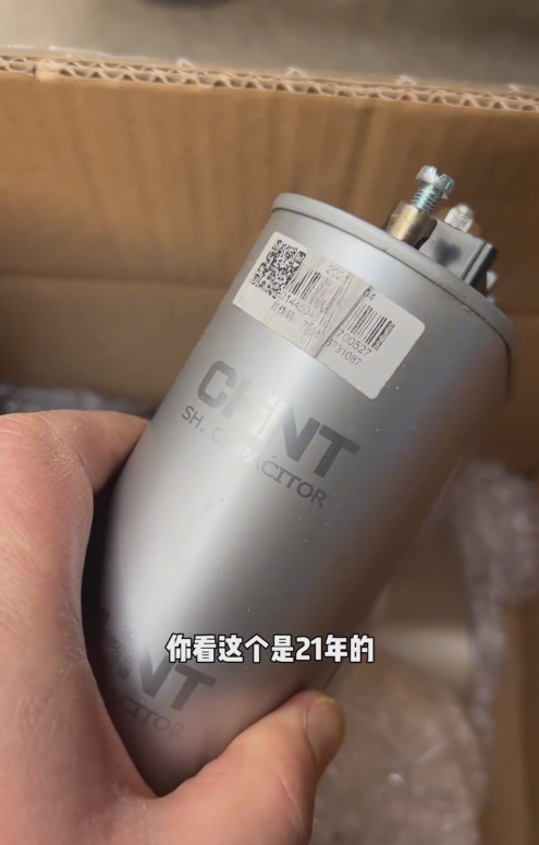

Chint BZMJ0.4-20-3 is a self-healing low-voltage shunt capacitor designed for three-phase 400V systems with a capacity of 20kvar. It is mainly used for reactive power compensation in low-voltage power grids, to improve power factor and reduce power loss. Its core features include rapeseed oil impregnation + metallized polypropylene film dielectric, self-healing capability and built-in discharge resistor, with an operating temperature range of -25℃~+50℃.
- Interprétation complète du modèle
| Code | Signification |
| B | Shunt Capacitor (Basic Category) |
| Z | Impregnant Type: Rapeseed Oil (Insulating and Heat-dissipating Medium) |
| MJ | Dielectric Material: Metallized Polypropylene Film (Core of Self-healing Function) |
| 0.4 | Rated Line Voltage: 0.4kV (400V) |
| 20 | Total Three-phase Capacity: 20kvar |
| 3 | Three-phase Connection Mode |
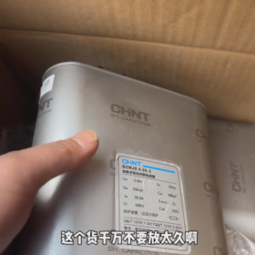
- Paramètres techniques de base (Spécifications faisant autorité)
| Paramètre | Valeur | Remarques |
| Tension nominale | 400V et (50Hz) | Line voltage, suitable for low-voltage distribution systems |
| Capacité nominale | 20kvar (Triphasé) | Benchmark value of reactive power compensation capability |
| Fréquence nominale | 50Hz (60Hz Compatible) | Standard frequency for industrial power grids |
| Capacity Tolerance | -5%~+10% | Complies with GB/T 12747.1 Standard |
| Courant nominal | 28.9UN | Calculated by I=Q/(√3×U)=20/(1.732×0.4) |
| Capacitance Value | Environ. 199µF (Triphasé) | Calculated by C=Q/(2πfU²)×10⁹ |
| Classe d'isolation | Self-healing Metallized Film | Automatically restores insulation after local breakdown |
| Discharge Performance | Reduces from √2Un to ≤75V within 3 minutes | Built-in discharge resistor ensures operational safety after power-off |
| Overcurrent Withstand Capability | 1.3 fois le courant nominal (Continuous Operation) | Tolerates grid voltage fluctuations |
| Overvoltage Withstand Capability | 1.1 times rated voltage (Continuous Operation) | Adapts to temporary grid voltage surges |
| Température ambiante | -25℃~+50℃ | Universal for indoor and outdoor applications |
| Relative Humidity | ≤50% at 40℃; ≤90% at 20℃ | Moisture-proof requirements |
| Altitude | ≤2000m | Applicable limit for plateau areas |
| Classe de protection | IP20 (Metal Enclosure) | Touch-proof, requires installation in distribution box |
| Executive Standards | GB/T 12747.1-2017 / CEI 60831-1:2014 | Dual certification of national and international standards |
- Core Product Features
- Self-healing Capability: When local breakdown occurs in the metallized film dielectric, the electrode metal layer evaporates instantly to form an insulating area, automatically restoring performance and extending service life.
- Conception de sécurité: Equipped with built-in discharge components, the residual voltage drops to a safe level within 3 minutes after power-off to prevent electric shock hazards.
- Reliable Insulation: The rapeseed oil impregnation system delivers excellent heat dissipation and insulation performance, suitable for harsh working conditions.
- Durable Structure: Metal enclosure combined with sealed structure resists mechanical impact, dust and moisture, ideal for industrial environments.
- High-efficiency Compensation: Low dissipation factor (tanδ≤0.0015) ensures high compensation efficiency and minimal self-power consumption.
- Scénarios d'application & Spécifications d'installation
Scénarios d'application:
0.4kV low-voltage distribution rooms, factory workshops and commercial building power distribution systems.
Occasions with concentrated inductive loads (moteurs, transformateurs, electric welders), to offset reactive power and improve power factor to ≥0.9.
Improve voltage quality, reduce line loss and transformer load.
Installation Points:
- Install in a ventilated and dry distribution box/cabinet free of corrosive gas, avoid direct sunlight exposure.
- Adopt three-phase star (Y) connection; connect phases A/B/C to corresponding phase lines respectively, and neutral line to N pole (si disponible).
- Connect in series with specialized fuses/circuit breakers (32Un recommandé) to prevent expansion of short-circuit faults.
- Reserve a heat dissipation space of ≥15cm; maintain appropriate spacing when multiple capacitors are connected in parallel.
- Tighten terminal connections according to the torque specified by the manufacturer (usually 6~8N·m) to prevent loosening and overheating.
- Live operation is strictly prohibited; wait for at least 3 minutes after power-off before touching the terminals.
- Entretien & Dépannage
Entretien courant:
Conduct quarterly visual inspections: check for no bulging, oil leakage or deformation; ensure terminals are free from overheating and oxidation.
Measure operating temperature: enclosure temperature ≤55℃; if abnormal, investigate overcurrent or harmonic issues.
Test capacitance value: recommend replacement if deviation exceeds ±15%.
Record operating current and voltage to ensure they are within rated ranges.
Défauts courants & Solutions:
| Phénomène de défaut | Causes possibles | Solutions |
| Enclosure Bulging/Oil Leakage | Overvoltage/overcurrent/high temperature/aging | Stop use immediately and replace with new products |
| Fuse Blowing | Internal short circuit/excessive harmonics/wiring errors | Inspect the circuit, eliminate faults and replace with fuses of the same specification |
| Poor Compensation Effect | Capacity attenuation/loose wiring/controller malfunction | Measure capacitance value, tighten terminals and inspect the compensation controller |
| Abnormal Overheating | Poor contact/high ambient temperature/overload | Clean contacts, improve ventilation and reduce load |
| Discharge Failure | Damaged discharge resistor | Conduct professional testing and replace the capacitor if necessary |
- Sélection & Replacement Recommendations
Correspondance de sélection:
Tension du système: 0.4 series is preferred for 400V systems; BZMJ0.45-20-3 is recommended for 450V systems.
Capacity Calculation: Configure 70%~90% of the reactive power of the load, or estimate 20%~30% of the transformer capacity.
Modèles alternatifs:
Same Series Upgrade: BZMJ0.45-20-3 (450V, suitable for scenarios with large voltage fluctuations)
Same Parameter Replacement: BSMJ0.4-20-3 (mineral oil impregnated, with similar performance)
Phase-separated Compensation: BZMJ0.4-20-3YN (independent three-phase adjustment, suitable for unbalanced loads)
- Avertissements de sécurité
- The capacitor is an energy storage device; short circuit is strictly prohibited. Ensure complete discharge before installation.
- All wiring, maintenance and replacement operations must be performed in the power-off state.
- Using the capacitor beyond the specified temperature, voltage or humidity range will significantly shorten its service life and cause potential safety hazards.
- Scrap capacitors must be disposed of as hazardous waste and shall not be discarded at will (containing oil and metal components).
 and 6ES7 235-0KD22-0XA8 (China CN), both hardware version 22 spare parts for S7-22X CPU maintenance.")


")


NH42-63-318x560.png "Commutateurs de transfert automatiques de type PC CHINT (ATS)NH42-63/4SZ")


