 Contacteur,disjoncteur,onduleur solaire,compteur électrique,batteries solaires

Paramètres de base
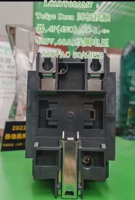
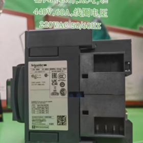
TeSys Deca Series 4-pole Contacteur (4P 4NO) is specially designed for non-inductive loads, suitable for AC-1 applications such as resistance furnaces and lighting systems.
| Paramètre | Valeur |
| Courant de fonctionnement nominal | 60UN (at ambient temperature ≤60°C) |
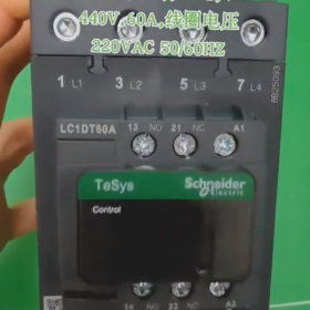
| Tension de fonctionnement nominale | Power circuit ≤690V AC/≤300V DC; Control circuit 220V AC 50/60Hz |
| Nombre de pôles | 4P. (4 contacts normalement ouverts) |
| Contacts auxiliaires | 1NON + 1Caroline du Nord (with NC mirror certification) |
| Durée de vie électrique | 1.4 millions d'opérations (60UN, AC-1, Ue≤440V) |
| Durée de vie mécanique | 6 millions d'opérations |
| Control Coil Characteristics | Inrush power: 160VA at 50Hz / 140VA at 60Hz |
| Holding power: 15VA at 50Hz / 13VA at 60Hz | |
| Classe de protection | IP20 (panneau avant) |
| Certifications | CEI, UL, ASC, CCC, CAE, Classification Society Certification, compliant with RoHS/REACh |
Dimensions d'installation
L×L×H: 122mm×70mm×120mm, Poids: 1.09kg
Méthodes de montage:
Montage sur rail DIN (standard 35mm)
Screw mounting (M4 screws, maximum torque 3.1Nm)
Wiring Diagram
Câblage du circuit principal
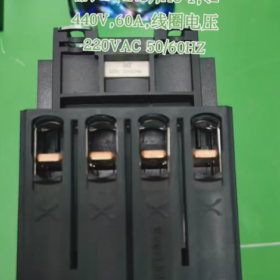
4-pole main contacts: L1/L2/L3/L4 (power input) → T1/T2/T3/T4 (load output)
| Marquage des bornes | Fonction | Capacité de câblage |
| L1~L4 | Contacts principaux | 1~35mm flexible/solid wires (without terminals) |
| T1~T4 | (power/load connection) | 1~25mm flexible wires (with terminals) |
| Tightening Torque | – | 8Nm for 25~35mmcables |
| 5Nm for 1~25mm cables |
Câblage du circuit de commande
Coil terminals: A1 (input), A2 (output), connected to 220V AC 50/60Hz control power supply
Contacts auxiliaires:
13-14: NON (normalement ouvert) contacts
21-22: Caroline du Nord (normalement fermé) contacts (with mirror certification)
| Marquage des bornes | Fonction | Capacité de câblage |
| A1, A2 | Coil connection | 1~4mm flexible/solid wires |
| 1~2.5mm flexible wires with terminals | ||
| 13-14 | Contacts auxiliaires | Same as coil terminals |
| 21-22 | ||
| Tightening Torque | – | 1.7Nm |
Précautions de câblage
- Power-off Operation: Cut off all power supplies and lock the circuit before wiring to prevent electric shock.
- Cable Selection:
Circuit principal: Copper conductors ≥6mm² are recommended for 60A loads.
Circuit de commande: Copper conductors ≥1mm² are recommended.
- Terminal Fastening:
Contacts principaux: Use a torque wrench to ensure the specified torque is achieved.
Control terminals: Tighten moderately (1.7Nm) to avoid terminal damage.
- Application of Auxiliary Contacts:
NO contacts are commonly used for self-locking control.
NC contacts are used for interlocking or fault indication.
Scénarios d'application
Control of industrial heating equipment (fours à résistance)
Main switch for lighting systems
On/off control of non-inductive loads
Power switching for star-delta motor starting (used with other contactors)
Mounting Methods of Schneider LC1DT60AM7 Contactor
Schneider LC1DT60AM7 contactor offers two standard mounting methods:
- Montage sur rail DIN (Recommandé)
Suitable for quick installation and replacement in control cabinets, compatible with standard 35mm DIN rail (DANS 60715 standard)
Mounting Steps:
- Align the rail clips on the back of the contactor with the upper edge of the 35mm DIN rail.
- Press the contactor downward while pushing it toward the rail until a “cliquez” le son est entendu, indicating the clips are locked in place.
Removal Method:
Gently pry the spring clips at the bottom of the contactor with a screwdriver and push it downward slightly to disengage from the rail.
- Direct Screw Mounting
Suitable for fixed installation scenarios without DIN rails
Mounting Steps:
- Use 3 M4 screws (spring washers and flat washers are recommended).
- Fix the contactor through the 3 mounting holes on its back: 2 at the top and 1 at the bottom.
- Tighten the screws with torque controlled within 3.1Nm to prevent housing damage.
Précautions d'installation
- Position and Orientation
Must be installed vertically (tilt angle ≤5°) to ensure the normal operation of internal mechanisms and heat dissipation.
The coil terminal A1 should face upward, complying with operational habits and visual indication requirements.
- Environment and Space
Select a dry and well-ventilated location, away from heat sources and humid areas.
Reserve sufficient space (≥100mm) for arc flash and heat dissipation to avoid damage to adjacent components.
- Exigences de mise à la terre
The metal mounting base must be properly grounded (PE) to ensure safety.
When using DIN rail mounting, the rail should be connected to an earthed conductive backplane.
- Wiring and Fixing
All terminals (including unused ones) must be tightened to ensure good contact.
Tightening torque for main circuit terminals: 8Nm for 25~35mm² cables; 5Nm for 1~25mm² cables.
Tightening torque for control circuit and auxiliary contact terminals: 1.7Nm.
The LC1DT60AM7 contactor provides flexible mounting options: 35mm DIN rail mounting is convenient and fast, suitable for standardized layout of control cabinets; M4 screw mounting is stable and reliable, applicable to special installation environments. Regardless of the method, vertical installation and good grounding must be ensured to guarantee the contactor’s performance and service life.


")


NH42-63-318x560.png "Commutateurs de transfert automatiques de type PC CHINT (ATS)NH42-63/4SZ")


