 Contattore,interruttore automatico,sensore,Codificatore,PLC,Convertitore

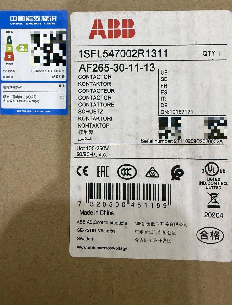

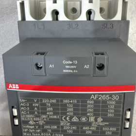
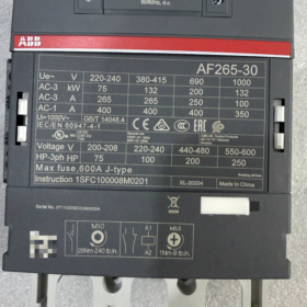
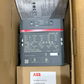
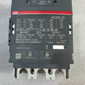
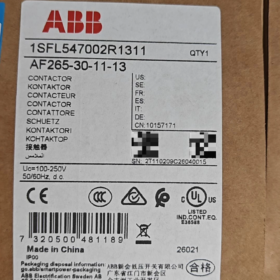
Ordine n.: 1SFL547002R1311;Materiale n.: 10157171
Serie: Serie AF 3-Contattore di polo con bobina elettronica universale AC/DC
- Decodifica del codice modello
| Segmento modello | Descrizione |
| DI | Serie AF, Bobina elettronica universale AC/DC ad ampio raggio, soppressione dei picchi incorporata; non è necessaria alcuna rete RC esterna o varistore |
| 265 | Corrente operativa nominale 265 A sotto AC‑3 a 400 V; Corrente termica convenzionale (AC‑1): 400UN |
| 30 | 3-polo, tutti i contatti principali normalmente aperti (NO); nessuna rete principale normalmente chiusa (NC) contatti |
| 11 | Contatti ausiliari integrati: 1NO +1NC |
| -13 | Codice bobina: 100‑250 V CA/CC (50/60 Hz + Compatibile con CC) |
✅Caratteristiche principali: La bobina singola supporta CA 100-250 V & CC 100-250 V; elevata tolleranza alle fluttuazioni di tensione; basso consumo energetico di mantenimento; funzionamento silenzioso.
- Specifiche elettriche principali
| Articolo | Valore |
| Numero di poli principali | 3P (3 contatti principali NO) |
| Corrente del motore AC‑3 (400 V) | 265 UN; Potenza motore 132 kW |
| Carico resistivo AC‑1 | 400 UN |
| Tensione nominale di isolamento Ui | 1000 V(CEI) /600 V(UL) |
| Tensione nominale di tenuta ad impulso Uimp | 8 kV |
| Tensione di controllo della bobina | 100‑250 V CA/CC 50/60 Hz‑CC |
| Contatti ausiliari | 1NA+1NC (montato frontalmente, non rimovibile) |
| Resistenza meccanica | 5 milioni di cicli operativi |
| Frequenza operativa massima | 300 operazioni/ora |
| Tensione di eccitazione | 80 % della tensione nominale della bobina inferiore; Tensione di caduta 55% della tensione nominale inferiore della bobina |
III. Ambientale & Parametri meccanici
| Articolo | Valore |
| Temperatura ambiente operativa (senza relè termico) | -40℃ ~ +70℃; ‑25℃ ~ +55℃ con relè di sovraccarico termico |
| Temperatura di conservazione | -40℃ ~ +70℃ |
| Altitudine senza declassamento | ≤3000m; declassamento richiesto sopra i 3000 m |
| Dimensioni complessive (L×A×P) | 140 mm × 225 mm × 180 mm |
| Peso netto | 3.9 kg |
| Tipo di terminale | Circuito principale: sbarra collettrice / terminali a bullone; Circuito di controllo: terminali a vite |
| Metodo di montaggio | Montaggio con vite su guida DIN verticale o piastra posteriore, è severamente vietato il montaggio laterale o capovolto |
Certificazioni: CCC, CE, UKCA, EAC, Certificazione navale DNV; Sicurezza funzionale: SIL2, ISO13849-1 Cat.B.
- Principio di funzionamento approfondito
I contattori della serie AF adottano una bobina elettronica di tipo raddrizzatore, diverso dai tradizionali contattori AC:
- Applicare 100-250 V CA o CC ad A1/A2; Il circuito elettronico interno rettifica l'ingresso in CC per pilotare la bobina elettromagnetica.
- Elevata potenza istantanea per il pull-in, quindi passare alla potenza di mantenimento CC bassa; riscaldamento della bobina molto inferiore rispetto alle tradizionali bobine AC.
- L'assorbitore di sovratensione TVS integrato dissipa la back-EMF alla diseccitazione della bobina. NON collegare reti RC esterne o varistori in parallelo; i dispositivi esterni potrebbero causare malfunzionamenti o danni permanenti.
- L'armatura magnetizzata CC elimina il rumore del ronzio CA a 50 Hz.
Definizione del terminale
Circuito principale lato linea: 1L1, 3L2, 5L3; lato carico: 2T1, 4T2, 6T3
Bobina: A1, A2 (non polare per AC & DC)
Contatti ausiliari: 13-14 (NO); 21-22 (NC)
- Lista di imballaggio standard & Accessori opzionali
Consegna standard
- AF265-30-11-13 Unità contattore ×1
- Manuale del prodotto, certificato di conformità
❗Non incluso: Relè termico, interblocco meccanico, blocchi aggiuntivi ausiliari, protezione di sicurezza del terminale.
Accessori ordinabili separatamente
| Accessorio | Funzione |
| TA275 TU | Relè di sovraccarico termico abbinato (80-275A) |
| CAL19‑11 | Blocco contatti ausiliari a montaggio laterale (1NA+1NC) |
| VM265 | Interblocco meccanico (per invertire il dovere) |
| AF-MTP | Copertura protettiva del terminale del circuito principale |
- Compatibilità tra marchi & Riferimento sostitutivo
⚠️Verificare la potenza nominale della bobina 100-250 V CA/CC e AC-3 265 A prima della sostituzione.
| Modello originale | Equivalente a adattamento diretto | Osservazioni |
| ABB AF265‑30‑11‑13 | A265‑30‑11 (EH265 precedente) | Le vecchie bobine della serie EH sono solo CA / Solo CC; le bobine non possono essere scambiate direttamente |
| Equivalenti della concorrenza | Siemens3RT1066‑6AP36; SchneiderLC1D245M7 | Nessuna bobina CA/CC nativa ad ampio raggio da 100‑250 V per Siemens/Schneider; selezionare la variante di bobina corretta |
VII. Scenari applicativi tipici
- Fan & avviamento del motore della pompa di grandi dimensioni (HVAC, aria condizionata centralizzata, trattamento dell'acqua)
- Compressore d'aria, controllo del motore dell'estrusore (110-132 motori trifase da kW)
- Commutazione del banco di condensatori (corrisponde alla classificazione AC-1 400A)
- Circuiti principali avanti/invertitore e stella-triangolo
- Marino & attrezzature orientate all'esportazione: compatibile con le tensioni di controllo globali (120 VCA/220 VCA universale)
VIII. Insidie della selezione & Restrizioni rigide
- ❌NON aggiungere soppressori di sovratensione esterni (Reti RC, varistori, diodi). Protezione contro le sovratensioni integrata fornita; dispositivi esterni causano danni alla bobina o mancata apertura.
- ❌Vietato il montaggio laterale o capovolto; È consentita solo l'installazione verticale in posizione verticale.
- ❌Il declassamento è obbligatorio sopra i 3000 m di altitudine; in caso contrario potrebbero verificarsi surriscaldamenti e bruciature dei contatti.
- ❌Non adatto per la commutazione ad alta frequenza (>300 operazioni/ora); utilizzare contattori in vuoto per applicazioni con servizio frequente.
- ✅Ampia tolleranza alla tensione di controllo: pull-in affidabile entro 80-250 V.
- Risoluzione dei problemi
| Sintomo | Causa ultima | Rimedio |
| Il contattore non si inserisce | Nessuna tensione tra A1‑A2; collegamenti allentati; guasto alla scheda elettronica interna della bobina | Misurare la tensione A1‑A2; stringere nuovamente i terminali; sostituire l'unità completa (La bobina AF non può essere sostituita separatamente) |
| Chiacchiere / pull-in intermittente | Tensione di controllo inferiore al limite minimo dell'80%.; ondulazione eccessiva dell'alimentatore | Garantire una tensione di ingresso ≥80 V; escludere una capacità del drive di uscita del PLC insufficiente |
| Riscaldamento eccessivo dei terminali del circuito principale | Coppia di serraggio insufficiente; sovraccarico; erosione da contatto / bruciando | Riserrare i bulloni delle sbarre collettrici; controllare la corrente di carico; sostituire il contattore per ablazione grave del contatto |
| I contatti rimangono chiusi dopo la diseccitazione (attaccarsi) | Saldatura dei contatti principali; tensione indotta residua sul cablaggio di controllo | Esaminare le condizioni di cortocircuito sul lato carico; eliminare la tensione residua indotta nei cavi di controllo |
Importante: La scheda elettronica della bobina serie AF è integrata all'interno dell'unità; i guasti alla bobina richiedono la sostituzione completa del contattore; non sono disponibili gruppi bobina di ricambio.
ABB AF265-30-11-13 Istruzioni per l'uso (Manuale compilato)
Documento manuale originale corrispondente n.: 1SFC100008M0201, dimensione del telaio applicabile: Serie AF190-205-265-305-370
Ordine n.: 1SFL547002R1311;Valutazione della bobina: 100-250 V CA/CC
⚠️Avviso di sicurezza: Installation and commissioning must be performed by qualified electrical personnel. Disconnect all upstream power supply prior to any wiring or maintenance work. Do NOT apply high-voltage dielectric test across A1/A2 coil terminals; electronic coil board will suffer permanent breakdown damage.
Sommario
- Panoramica del prodotto
- Modello & Definizione del terminale
- Specifiche di installazione
- Cablaggio & Coppia di serraggio
- Coil Operating Instructions (AF Electronic Coil Key Notes)
- Commissioning Procedure
- Accessory Mounting
- Programma di manutenzione & Elementi di ispezione
- Risoluzione dei problemi
- Operazioni vietate
- Access to Original PDF Manual
- Panoramica del prodotto
AF265-30-11-13 is a 3-pole contactor with integrated wide-range electronic coil and built-in surge suppression. External RC / varistor suppressors are prohibited.
AC-3-400 V: 265 UN, motor rating 132 kW
AC-1 resistivo: 400 UN
Contatti ausiliari incorporati:1NO(13-14)+1NC(21-22)
Valutazione della bobina:100-250 V CA/CC; pull-in ≥80 %Uc; drop-out ≤55 %Uc
Resistenza meccanica:5 milioni di cicli; max operating frequency 300 operazioni/ora
Temperatura operativa:-40 ℃~+70 ℃ (senza relè termico); no derating ≤3000 m altitude.
- Definizione del terminale
| Circuito | Terminale n. | Descrizione |
| Main circuit line‑side | 1L1, 3L2, 5L3 | 3-ingresso alimentazione di fase |
| Lato carico del circuito principale | 2T1, 4T2, 6T3 | Motore / connessione di carico |
| Bobina | A1, A2 | Non polare per AC/DC; classificato per 100‑250 V CA/CC |
| Ausiliario incorporato NO | 13-14 | Normalmente aperto |
| NC ausiliaria incorporata | 21‑22 | Normalmente chiuso |
Il blocco aggiuntivo ausiliario CAL19-11 può essere montato sul lato sinistro dell'unità.
- Specifiche di installazione
- Orientamento di montaggio: solo installazione verticale su montante (terminali principali verticali su-giù). È severamente vietato il montaggio laterale o capovolto.
- Due opzioni di installazione:
Fissaggio a vite sulla piastra posteriore: 4 1 bullone M8
Montaggio su guida DIN35mm (Per AF265 di grande formato, il montaggio con viti è preferibile rispetto al montaggio su guida).
- Dissipazione del calore dell'armadio: È possibile montare più unità fianco a fianco senza spazi vuoti; nessun declassamento fino a 70 ℃ ambiente. Il declassamento è obbligatorio per l'altitudine >3000 M.
- Dimensione minima consigliata dell'armadio: ≥900×750×300mm, per garantire un'adeguata ventilazione dall'alto verso il basso.
- Prevent metal chips and drilling dust from entering contactor enclosure during installation.
- Cablaggio & Coppia di serraggio (Most overheating originates from insufficient torque)
| Posizione del terminale | Dimensione del bullone | Recommended Tightening Torque | Requisiti dei cavi |
| Main circuit L/T terminals | M12 | 24 N·m | Copper busbar / ATK300 lugs; 75 ℃ rated copper conductors; direct aluminum conductor connection prohibited |
| Coil A1‑A2 | M4 | 1.2‑1.5 N·m | 0.75‑2.5 mm² copper wire |
| Contatti ausiliari | M4 | 1.2 N·m | 0.75‑2.5 mm² copper wire |
ATK300 crimped lugs are recommended for main circuit. Fit AF-MTP terminal safety shield over bare live conductors for touch-protection.
- Coil Operating Instructions (AF Electronic Coil Key Notes)
- A1/A2 coil terminals are non-polar; either AC or DC 100-250 V may be applied directly.
- Built-in on-board TVS surge suppression. External RC snubber, varistor or freewheeling diode are strictly forbidden. External surge devices will burn coil board or cause failure to open.
- Accoglienza: chiusura affidabile ≥80% ×100V = 80V.
- Ritirarsi: apertura affidabile ≤55%Uc.
- Basso consumo energetico di mantenimento; funzionamento silenzioso, nessun ronzio.
- ❗La scheda bobina elettronica è integrata nell'unità principale. La bobina non può essere sostituita separatamente; è necessaria la sostituzione dell'intera unità in caso di guasto della bobina.
- Prova di tenuta dielettrica: Non eseguire mai il test dell'hipot sui terminali della bobina A1-A2; distruggerà il circuito elettronico.
- Passaggi di messa in servizio
- Tutta l'alimentazione scollegata; verificare il cablaggio completo e i valori di coppia; verificare che il coperchio della camera ad arco sia completamente inserito e intatto.
- Confermare la corrispondenza della tensione di alimentazione di controllo -13 classificazione della bobina (100-250 VCA/CC).
- Mantenere l'alimentazione trifase principale scollegata; energizzare solo il circuito di controllo per il test funzionale a vuoto:
Applicare tensione ad A1-A2: il contattore dovrà intervenire prontamente; diseccitare per un rilascio immediato senza vibrazioni.
Verificare la logica del contatto ausiliario: 13-14 aprire/chiudere, 21-22 chiudere/aprire come previsto.
- Procedere ad alimentare l'alimentazione principale solo dopo aver superato con successo il test a vuoto, eseguire una prova di caricamento.
- Funziona a pieno carico per almeno 30 minuti; misurare l'aumento della temperatura terminale; aumento accettabile della temperatura dell'alloggiamento ≤60K.
- Accessory Mounting
- CAL19-11 (blocco ausiliario a montaggio laterale): Far scorrere nella fessura sul lato sinistro del contattore fino al completo bloccaggio; aggiunge contatti 1NO+1NC.
- Interblocco meccanico VM265: per l'applicazione dell'interblocco avanti-indietro; sono necessari due contattori in coppia.
- Relè di sovraccarico termico TA275-DU: installazione con montaggio dal basso; Intervallo di temperatura operativa del relè: -25~+55℃.
- Schermo di sicurezza del terminale del circuito principale AF-MTP, impedisce il contatto accidentale delle sbarre sotto tensione.
Tutti gli accessori sono ordinabili separatamente, non incluso nella consegna standard.
- Manutenzione periodica & Ispezione
Eseguire solo con l'alimentazione completamente disconnessa! Intervallo di manutenzione: ogni 12 mesi per un ambiente pulito; ogni 6 mesi per la polvere / condizioni di vibrazioni elevate.
- Stringere nuovamente tutti i terminali del circuito principale alla coppia specificata.
- Ispezionare il coperchio della camera d'arco per individuare eventuali crepe, depositi di carbonio o accumulo di polveri metalliche; sostituire la camera ad arco in caso di combustione grave.
- Ispezionare l'erosione del contatto principale; sostituire l'unità completa in caso di forte usura o saldatura a contatto. Non sono disponibili pezzi di ricambio per contatti separati per AF265.
- Pulire la polvere esterna. NON soffiare aria compressa direttamente nella custodia, la polvere metallica può danneggiare l'elettronica interna della bobina.
- Verificare la temperatura ambiente dell'armadio e i percorsi di ventilazione liberi.
- Test funzionale della commutazione dei contatti ausiliari.
Nota: Le unità con telaio AF190-AF370 non dispongono di gruppi di contatti separati riparabili; è necessaria la sostituzione dell'intera unità in caso di danni ai contatti.
- Tabella per la risoluzione dei problemi
| Sintomo | Causa | Rimedio |
| Il contattore non si inserisce | Nessuna tensione A1‑A2; collegamenti allentati; guasto della bobina elettronica interna | Misurare la tensione A1‑A2; stringere nuovamente i terminali; sostituire l'intera unità |
| Chiacchiere / rimbalzi ripetuti | Tensione di controllo inferiore all'80% minimo; Azionamento di uscita PLC insufficiente; tensione residua indotta nel cablaggio di controllo | Verificare la tensione di alimentazione; aggiornare la capacità dell'unità PLC; eliminare la tensione residua indotta |
| Non si apre dopo la diseccitazione (attaccarsi) | Saldatura del contatto principale; tensione indotta residua sul circuito di controllo; componenti esterni di sovratensione rimossi in modo incompleto | Individuare il guasto di cortocircuito sul lato carico; eliminare la tensione indotta; rimuovere completamente l'RC esterno / dispositivi varistori |
| Riscaldamento eccessivo nei terminal principali | Coppia di serraggio insufficiente; cavo sottodimensionato / sbarra collettrice; condizione di sovraccarico | Riserrare i dispositivi di fissaggio; ricalcolare la portata del conduttore; misurare la corrente di carico effettiva |
| La bobina brucia immediatamente dopo l'eccitazione | Test Hipot applicato ad A1‑A2; dispositivi di sovratensione esterni; la tensione di alimentazione supera il limite superiore di 250 V | Vietare l'hipot sui terminali della bobina; rimuovere i componenti esterni di sovratensione; limitare la tensione di controllo entro l'intervallo nominale di 100‑250 V |
- Operazioni vietate
❌Vietato il montaggio laterale o capovolto;
❌Ipote / vietato il test megger sui terminali della bobina A1/A2;
❌Smorzatore RC esterno, vietati varistore o diodo di ricircolo;
❌Non eccedere 300 operazioni/frequenza di commutazione oraria;
❌Funzionamento senza declassamento in base all'altitudine >3000 Sono proibito;
❌Non tentare di smontare il gruppo elettronico della bobina interna; nessun pezzo di ricambio riparabile.
- Access to Original PDF Manual
- Visita la pagina web ufficiale del prodotto ABB, ricerca numero ordine 1SFL547002R1311 → sezione Download, scarica la scheda tecnica e le istruzioni d'uso.
- Numeri di riferimento del documento: Istruzioni per l'uso: 1SFC100008M0201 (multilingue compreso il cinese); Manuale di servizio 1SFC101044M0201.







NH42-63-318x560.png "Commutatori automatici di tipo PC CHINT (ATS)NH42-63/4SZ")



