 Contattore,interruttore automatico,sensore,Codificatore,PLC,Convertitore

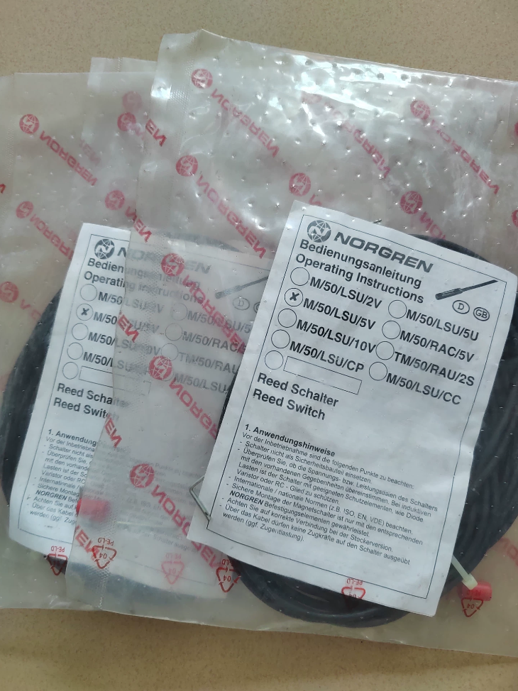

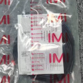
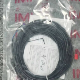
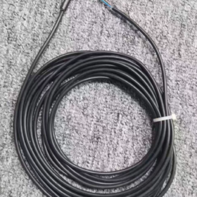
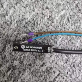
Ripartizione del modello
M/50: Serie di prodotti, interruttore di prossimità magnetico a cilindro
LSU: Tipo ad ancia, Normalmente aperto (NO), con indicatore LED, uscita del cavo
5: Lunghezza del cavo 5 metri
V: Versione universale ad ampio voltaggio (10~170 V CA/CC)
Applicazione principale
Rileva la posizione di corsa completa dei pistoni dei cilindri pneumatici (segnali di posizione estesi/retratti per feedback a PLC o relè)
- Specifiche elettriche principali
| Parametro | Specifica |
| Principio di funzionamento | Contatto Reed (azionamento magnetico meccanico) |
| Configurazione dei contatti | Normalmente aperto (NO): aperto senza magnete, chiuso vicino all'anello magnetico |
| Tensione operativa | 10~170 V CA/CC; compatibile con i sistemi generali da 240 V CA/CC |
| Corrente di commutazione massima | 0.18 UN |
| Potenza di commutazione massima | 10 W |
| Tempo di risposta | 1.8 SM |
| Indicatore luminoso | LED giallo integrato, illuminato su azionamento magnetico |
| Protezione dall'ingresso | IP66 (antipolvere, protetto contro gli spruzzi ad alta pressione) |
| Temperatura operativa | -20 ℃ a +80 ℃ |
| Specifiche del cavo | 5m di cavo in PVC, 2-nucleo 0,25 mm² |
| Standard di conformità | IN 60947-5-2, RoHS, PORTATA |
| Origine | Polonia |
- Meccanico & Installazione
3.1 Cilindri compatibili
Cilindri a profilo Norgren serie RA/8000 e KA/8000; staffe di montaggio ad anello/morsetto abbinate (Serie QM/33), compatibile con diametri 10/20/25/32/40/50/63/80/100 mm.
3.2 Metodi di montaggio
Cilindri profilati con scanalatura a T: Far scorrere l'interruttore direttamente nella scanalatura a T del cilindro, non sono necessarie parentesi aggiuntive
Cilindri a tiranti tondi: Fissato tramite staffe di fissaggio metalliche opzionali
3.3 Materiale dell'alloggiamento
Plastica tecnica, resistente alla contaminazione dell'olio e alle vibrazioni industriali
- Guida alla selezione di più serie (Differenziazione rapida)
- M/50/LSU/2V: 2-cavo da un metro, tutti gli altri parametri sono identici alla variante 5V
- M/50/LSU/5U: 5-cavo da un metro, modello DC a bassa tensione (10~30 VCC)
- Serie M/50/EHP: Elettronica a stato solido senza contatto (PNP/NPN), Sostituzione di lunga durata ad alta frequenza per interruttori Reed
- Scenari applicativi
Linee di assemblaggio automatizzate, macchine per l'imballaggio, attrezzature pneumatiche per macchine utensili
Rilevamento del limite della corsa per cilindri per la movimentazione dei materiali, rilevamento della posizione per cilindri di apparecchiature di stampaggio
Feedback di posizione per attuatori pneumatici generali, compatibile con quadri elettrici AC/DC
- Precauzioni operative
- I contatti Reed non possono pilotare carichi pesanti; per il trasferimento del segnale è necessario utilizzare un relè di interposizione. È vietato l'azionamento diretto delle bobine magnetiche.
- Evitare ambienti con forti campi magnetici o forti interferenze elettromagnetiche provenienti da apparecchiature di saldatura per evitare falsi inneschi.
- Raggio minimo di curvatura del cavo ≥ 10× diametro esterno del cavo; protezione del tubo corrugato consigliata per apparecchiature a vibrazione continua.
- Sostituirli con interruttori elettronici M/50 a stato solido se la temperatura ambiente supera gli 80 ℃.
- Numeri di parte per accessori coordinati
Staffa di bloccaggio per foro Ø20: QM/33/020/22
Staffa di bloccaggio per foro Ø32: QM/33/432/22
Clip di fissaggio per cambio rapido: QM/27/2/1
Manuale di installazione ufficiale completo dell'interruttore magnetico Reed IMI Norgren M/50/LSU/5V
Documentare le informazioni di base
Modello: M/50/LSU/5V (M50LSU5V)
Tipo di prodotto: Interruttore di posizione magnetico reed normalmente aperto, LED giallo integrato, 5Cavo a 2 fili da m, ampia tensione 10~170 V CA/CC
Cilindri compatibili: Norgren RA/8000 & Cilindri con profilo cava a T serie KA/8000, cilindri a tiranti tondi
Protezione dall'ingresso: IP66
Standard: IN 60947-5-2, RoHS, PORTATA
Sommario
- Ispezione del disimballaggio & Verifica del modello
- Installazione meccanica (Due soluzioni: Profilo con scanalatura a T / Cilindri con tiranti rotondi)
- Elenco di selezione per staffe di montaggio corrispondenti
- Specifiche del cablaggio elettrico & Schemi elettrici
- Procedure di messa in servizio
- Ambientale & Divieti di installazione (Restrizioni critiche)
- Matrice di risoluzione dei problemi
- Manutenzione ordinaria
- Specifiche tecniche di riferimento rapido
1 Ispezione del disimballaggio & Verifica del modello
1.1 Ispezione delle merci in entrata
- Verificare il modello inciso al laser sul corpo dell'interruttore: M/50/LSU/5V; confermare la lunghezza del cavo di 5 metri
- Ispezionare l'alloggiamento per eventuali crepe, radice del cavo per danni, finestra di visualizzazione LED intatta
- Accessori: Vite di fissaggio di fissaggio preinstallata sull'unità; per i cilindri tondi le staffe di bloccaggio devono essere ordinate separatamente
1.2 Definizione del segmento del modello
M/50: Serie di interruttori di prossimità magnetici
l: Dotato di indicatore LED
Sono: Reed per uso generale normalmente aperto, tipo di uscita del cavo
5: 5-lunghezza del cavo in metri
V: Modello universale ad ampio voltaggio, 10~170 V CA/CC
2 Guida operativa per l'installazione meccanica
2.1 Cilindri con profilo con scanalatura a T (Serie Norgren RA/KA, Montaggio consigliato)
- Allentare la vite di fissaggio a testa piatta sulla coda dell'interruttore e aprire la fessura della clip
- Inserire completamente la clip dell'interruttore nella scanalatura a T sul lato del cilindro, far scorrere nella posizione di rilevamento del bersaglio (posizione del magnete alla completa estensione/retrazione del cilindro)
- Perfezionare la posizione orizzontale: Punto di attivazione ottimale quando il LED giallo rimane acceso fisso mentre il magnete del pistone passa accanto all'interruttore
- Stringere la vite di fissaggio della coda con un cacciavite piatto, coppia 0,8~1,0 N·m per evitare spostamenti dovuti alle vibrazioni
- Far passare l'uscita del cavo verso il basso o lateralmente; è vietato il percorso ascendente per evitare accumuli di acqua
2.2 Cilindri con tiranti rotondi (Nessuna scanalatura a T, Montaggio su staffa a morsetto)
- Selezionare la fascetta metallica della serie QM/33 corrispondente in base alla dimensione del foro del cilindro
- Montare il morsetto sulla canna del cilindro, pre-serrare le viti del morsetto e far scorrere nella posizione di rilevamento
- Agganciare l'interruttore M/50 al fermo a morsetto integrato, fissare la vite di fissaggio dell'interruttore
- Stringere completamente il morsetto per evitare scivolamenti durante il funzionamento; coppia di serraggio 1,2~1,5 N·m
2.3 Standard di posizione di montaggio
La superficie attiva è a filo con la parete esterna del cilindro, gioco zero, nessun interstrato metallico
Distanza minima di 20 mm tra due interruttori su un cilindro per evitare interferenze magnetiche reciproche
Tenersi lontani da forti inserti magnetici sui cappucci terminali dei cilindri (magneti tampone)
3 Elenco dei codici articolo delle staffe di montaggio corrispondenti
| Accessorio N. parte. | Applicazione | Dimensioni foro compatibili |
| QM/27/2/1 | Clip universale per cilindri profilati (clip identica premontata per l'interruttore) | Tutti i cilindri con scanalatura a T |
| QM/33/010/22 | Morsetto in alluminio per cilindri tondi | Ø10 |
| QM/33/020/22 | Morsetto in alluminio per cilindri tondi | Ø20/25 |
| QM/33/432/22 | Morsetto in alluminio per cilindri tondi | Ø32/40 |
| QM/33/463/22 | Morsetto in alluminio per cilindri tondi | Ø50/63/80/100 |
4 Specifiche del cablaggio elettrico (Capitolo fondamentale)
4.1 Definizione del cavo (2-cavo in PVC con anima, 0.25mm²)
Filo marrone (BN): Potere positivo / Linea sotto tensione CA
Filo blu (QUESTO): Potere negativo / Linea neutra CA
I contatti reed interni normalmente aperti chiudono il circuito quando l'anello magnetico si avvicina, il LED giallo si illumina
4.2 Due schemi di cablaggio standard
Schema A: Ingresso digitale PLC di comando (Più comune)
- Sistema DC24V: BN collegato a +24V, BN cablato al terminale di ingresso del PLC, Terminale comune del PLC collegato a 0 V
- Sistema AC220V: BN collegato a Live (l), BU collegata al neutro (N) del modulo di ingresso CA PLC
> AVVERTIMENTO: La corrente di commutazione massima dei contatti reed è 0,18 A; è severamente vietato l'azionamento diretto delle bobine dei solenoidi!
Schema B: Relè di interposizione per trasferimento di carichi pesanti
- Bobina relè cablata in serie con BN & BU va in giro
- I contatti relè controllano carichi ad alta corrente, comprese elettrovalvole e spie luminose
4.3 Restrizioni critiche di cablaggio
- Nessuna energizzazione in condizioni di assenza di carico (il circuito scarico brucia istantaneamente i contatti reed tramite un arco elettrico)
- Separare il cablaggio dei segnali dai cavi di potenza (inverter, conduttori del motore), distanza minima di 10 cm per evitare false attivazioni indotte da interferenze
- Raggio minimo di curvatura del cavo ≥10× diametro esterno del cavo; È vietato piegare/tirare ripetutamente la radice del cavo
- Isolare l'alimentazione dell'intero armadio prima del cablaggio per evitare scosse elettriche e bruciature dei contatti
4.4 Protezione del percorso dei cavi
Attrezzatura vibrante: Far passare i cavi attraverso il tubo corrugato; riservare 5~8 cm di gioco alla radice del cavo dell'interruttore
Nebbia d'olio & ambienti di spruzzatura: Avvolgere i giunti dei cavi con nastro impermeabile; sigillare i punti di ingresso dei cavi all'interno degli armadi di controllo
5 Procedure standard di messa in servizio dell'unità completa
Fare un passo 1 Calibrazione della posizione meccanica
Azionare manualmente il pistone del cilindro per far scorrere lentamente il magnete incorporato attraverso la zona di rilevamento dell'interruttore
Magnete nella posizione di rilevamento: Il LED giallo rimane costantemente acceso
Magnete lontano dalla posizione di rilevamento: LED completamente spento
Se il LED lampeggia, posizione orizzontale dell'interruttore con regolazione precisa per un'attivazione stabile senza stroboscopia
Fare un passo 2 Test dei segnali elettrici
- Accendere, misurare la continuità del circuito tramite multimetro collegato in serie
- Magnete nella zona di rilevamento: Circuito chiuso (resistenza prossima a 0Ω)
- Magnete lontano dalla zona di rilevamento: Circuito aperto (resistenza infinita)
Fare un passo 3 Verifica automatizzata del ciclo
Eseguire il ciclo alternativo del cilindro 10 volte senza carico; confermare l'uscita stabile del segnale ad ogni fine corsa senza perdita di segnale o false attivazioni
6 Ambientale & Divieti di installazione (Operazioni proibite)
- Limite di temperatura: Intervallo operativo -20℃ ~ +80℃; sostituire con interruttori elettronici M/50 sopra gli 80°C
- Interferenza magnetica: Tenere lontano dalle apparecchiature di saldatura, potenti magneti permanenti, servomotori, cavi di uscita dell'inverter per evitare operazioni errate
- Protezione dagli impatti: Vietare di colpire o far cadere l'unità interruttore; Il tubo lamellare interno in vetro si frattura facilmente in caso di impatto
- Ambienti chimici: Installare coperture protettive in acido forte, ambienti alcalini o solventi ad alta concentrazione; l'alloggiamento in plastica si corroderà e si spezzerà
- Lavaggio a pressione: La classificazione IP66 resiste solo agli spruzzi a bassa pressione; il getto d'acqua diretto ad alta pressione sulla radice del cavo provoca l'ingresso di acqua e il guasto dell'unità
- Operazione sovraccarica: La potenza di commutazione non deve superare i 10 W; relè di interposizione obbligatorio per carichi di potenza maggiore
7 Matrice di risoluzione dei problemi
| Sintomo di guasto | Causa ultima | Azioni correttive graduali |
| LED spento, nessun segnale quando il magnete raggiunge il punto di rilevamento | 1. Cablaggio rotto/invertito | 1. Tagliare la corrente, crimpare nuovamente i terminali e verificare il cablaggio marrone/blu |
| 2. Montaggio interruttore allentato/spostato | 2. Stringere la vite di fissaggio e ricalibrare la posizione | |
| 3. Danni all'ancia interna | 3. Sostituirlo con una nuova unità M/50/LSU/5V | |
| LED tremolante, perdita di segnale intermittente | 1. Distanza eccessiva tra interruttore e magnete | 1. Montare l'interruttore a filo contro la parete del cilindro per eliminare il gioco |
| 2. Grave interferenza elettromagnetica | 2. Instradare i cavi di segnale separatamente e aggiungere la schermatura | |
| 3. Rottura del filo interno alla radice del cavo | 3. Tagliare il segmento di cavo danneggiato e riterminare | |
| L'interruttore si brucia subito dopo l'accensione | 1. Azionamento diretto di carichi magnetici pesanti | 1. Installare un relè di interposizione per il trasferimento del carico |
| 2. Tensione in ingresso superiore a 170 V | 2. Abbinare la tensione del sistema e aggiungere un regolatore di tensione | |
| 3. Eccitazione in cortocircuito senza carico | 3. Il carico in serie deve essere montato prima di energizzare il circuito | |
| L'interruttore scorre fuori posizione durante il funzionamento del cilindro | Coppia di serraggio delle viti insufficiente, allentamento dovuto alle vibrazioni | Stringere nuovamente la vite di fissaggio a 0,8~1 N·m; aggiungere rondelle antiallentamento per macchinari ad alte vibrazioni |
8 Specifiche di manutenzione ordinaria
- Ispezione giornaliera: Controllare lo stato del trigger LED, ispezionare i cavi per verificare la presenza di abrasioni o crepe
- Manutenzione settimanale: Pulire l'olio e la polvere dalla superficie dell'interruttore; prevenire l'adesione di detriti metallici all'alloggiamento
- Ispezione mensile: Serrare nuovamente le viti di fissaggio per evitare l'allentamento dovuto alle vibrazioni a lungo termine
- Calibrazione semestrale: Verificare la stabilità del segnale; mantenere unità sostitutive di ricambio per la linea di produzione di massa
9 Specifiche tecniche principali del prodotto (Riferimento per l'installazione)
| Parametro | Specifica M/50/LSU/5V |
| Elemento sensibile | Tubo a lamella, Normalmente aperto (NO) |
| Tensione operativa | 10~170 V CA/CC |
| Corrente di commutazione massima | 0.18UN |
| Potenza di commutazione massima | 10W |
| Tempo di risposta | 1.8SM |
| Indicatore luminoso | LED giallo, illuminato quando chiuso |
| Specifiche del cavo | 5M, 2×0,25 mm² PVC |
| Protezione dall'ingresso | IP66 |
| Temperatura operativa | -20℃ ~ +80 ℃ |
| Materiale dell'alloggiamento | Plastica tecnica ignifuga |
| Norma di conformità | IN 60947-5-2 |
Difetti comuni, Cause & Soluzioni correttive per Norgren M/50/LSU/5V (M50LSU5V) Interruttore magnetico
Questo interruttore magnetico a contatto reed presenta quattro categorie di guasti principali: nessun segnale in uscita, segnale tremolante, corpo interruttore bruciato, spostamento meccanico. Debolezze intrinseche dell'interruttore reed (suscettibile alla corrente elevata, impatto pesante e temperatura elevata) sono i principali fattori scatenanti del fallimento.
1 Colpa 1: LED spento, nessun segnale in uscita quando arriva il magnete del cilindro (Guasto più comune)
Potenziali cause
- Offset di montaggio meccanico
La vite di fissaggio allentata sposta l'interruttore fuori dalla zona di rilevamento del magnete; distanza eccessiva tra interruttore e canna del cilindro.
- Difetti di cablaggio
Conduttori rotti a causa di piegature ripetute alla radice del cavo, crimpature dei terminali allentate, isolamento del cavo tagliato da bordi metallici taglienti che provocano cortocircuiti/aperti circuiti (Insensibile alla polarità AC/DC).
- Magnete cilindrico anomalo
Magnete del pistone caduto o smagnetizzato; cancellazione del campo magnetico da due interruttori troppo ravvicinati; interferenze provenienti dai magneti del buffer del cilindro.
- Danno fisico al tubo lamellare interno
L'ancia di vetro si rompe a causa dell'impatto durante il trasporto o l'installazione; guasto permanente dell'ancia a temperature prolungate superiori a 80 ℃.
- Tensione di alimentazione non corrispondente
La tensione di ingresso supera i 170 V nominali, componenti interni in fiamme.
Azioni correttive
- Riportare l'interruttore in posizione centrale del magnete, stringere le viti (0.8Coppia di ~1 Nm) e montare a filo contro la parete del cilindro senza spazi vuoti.
- Interrompere l'alimentazione e testare la continuità del cavo; tagliare le sezioni danneggiate del cavo e crimpare nuovamente i terminali; riservare un lasco alla radice del cavo per eliminare la tensione.
- Sostituire il magnete del pistone del cilindro; mantenere una distanza ≥20 mm tra due interruttori e tenersi lontani dai magneti del buffer del cappuccio terminale.
- Le fratture dell'ancia richiedono la sostituzione completa dell'unità; Interruttori elettronici M/50/EHP consigliati per ambienti ad alta temperatura (difetti minori riparabili in condizioni di bassa temperatura).
- Limitare la tensione del sistema entro 10~170 V CA/CC; montare stabilizzatori di tensione per sistemi di sovratensione.
2 Colpa 2: LED tremolante, segnali intermittenti, frequente rilevamento di false corse da parte del PLC / perdita di segnale
Potenziali cause
- Il montaggio allentato dell'interruttore crea lievi spostamenti dovuti alle vibrazioni dell'apparecchiatura, rilevamento del magnete instabile.
- Grave interferenza elettromagnetica: Cavi di segnale instradati nella stessa canalina del motore, inverter e cavi di alimentazione per saldatura.
- La forza ridotta del magnete riduce il campo di rilevamento effettivo, causando sfarfallio nelle posizioni di soglia.
- Rottura parziale del conduttore interno del cavo che crea circuiti aperti/chiusi intermittenti sotto sforzo meccanico.
- I magneti permanenti esterni o i magneti degli utensili contrastano i campi magnetici del pistone del cilindro.
Azioni correttive
- Stringere nuovamente le viti di fissaggio; installare rondelle antiallentamento per apparecchiature ad alte vibrazioni.
- Far passare i cavi di segnale in condotti separati con una separazione minima di 10 cm dai cavi di alimentazione.
- Sostituire il magnete del pistone incorporato nel cilindro.
- Tagliare il segmento di cavo danneggiato e riterminarlo; spostare l'unità lontano da magneti permanenti esterni.
3 Colpa 3: L'interruttore si brucia immediatamente all'accensione, funzionalità zero dopo l'energizzazione
Causa principale (Errore fatale per gli interruttori Reed)
- Azionamento diretto di elettrovalvole o bobine di relè pesanti
Potenza di commutazione massima dell'unità solo 10 W / 0.18UN; La corrente di picco induttiva proveniente dalle bobine del solenoide perfora istantaneamente i contatti reed.
- Eccitazione senza carico nel circuito, burnout del contatto causato da un arco elettrico istantaneo.
- L'arco continuo dei contatti dovuto a frequenti commutazioni durante il funzionamento a 220 V CA provoca la saldatura e l'erosione dei contatti.
- Cortocircuito positivo-negativo del cavo; la corrente intensa brucia il LED interno e il tubo reed.
Azioni correttive
- Relè di interposizione obbligatorio per il trasferimento del segnale: L'interruttore eccita solo la bobina del relè; i contatti relè controllano le elettrovalvole.
- Non alimentare mai i circuiti scarichi; il carico in serie deve essere installato prima del collegamento all'alimentazione.
- Sostituirlo con interruttori elettronici senza contatto M/50/EHP (PNP/NPN, usura dell'arco pari a zero) per applicazioni di commutazione ad alta frequenza.
- Individuare i punti di cortocircuito dell'isolamento del cavo e rinforzare la protezione dell'isolamento.
4 Colpa 4: Saldatura dei contatti, Il LED rimane acceso dopo che il magnete si è allontanato, il segnale non si interrompe
Cause
- Il sovraccarico a lungo termine e l'arco di carico induttivo fondono insieme i contatti reed.
- Fatica da contatto del metallo e saldatura dovuta a cicli frequenti combinati con temperatura ambiente elevata.
- Una tensione di alimentazione eccessiva amplifica l'arco e accelera la fusione dei contatti.
Azioni correttive
I contatti reed saldati non possono essere riparati; sostituire l'intero gruppo interruttore. Montare relè di interposizione a valle per eliminare la formazione di archi di contatto.
5 Colpa 5: Spostamento scorrevole automatico dell'interruttore durante il funzionamento prolungato dell'apparecchiatura
Cause
- Coppia di serraggio insufficiente sulle viti di fissaggio.
- Vibrazioni e urti continui derivanti dal funzionamento della linea di produzione.
- Clip di fissaggio della scanalatura a T usurate che riducono la forza di bloccaggio.
Azioni correttive
Stringere nuovamente le viti alla coppia standard; aggiungere rondelle antiallentamento per apparecchiature vibranti; sostituire l'intera unità interruttore se i fermagli di fissaggio sono usurati.
6 Guasti latenti indotti dall'ambiente operativo
- Ambienti ad alta temperatura (>80℃)
Rapido declino della sensibilità dell'ancia con conseguente mancato azionamento e durata di servizio drasticamente ridotta; guasto permanente dell'unità in condizioni di calore elevato prolungato.
- Immersione in nebbia d'olio o fluido da taglio
La classificazione IP66 resiste solo all'esposizione agli spruzzi; la penetrazione prolungata del liquido alla radice del cavo provoca ossidazione interna e rottura del filo.
- Vapori chimici corrosivi
L'alloggiamento in plastica invecchia e si rompe, L'ingresso di umidità danneggia il tubo lamellare e il gruppo LED.
7 Differenziazione rapida: Guasti esclusivi dell'interruttore Reed e guasti dell'interruttore elettronico
Modalità di guasto uniche del modello reed M50LSU5V: Saldatura dei contatti, burnout da arco elettrico, vulnerabilità ai picchi di corrente elevati, danni interni dovuti a shock da impatto.
Gli interruttori elettronici M/50/EHP non contengono contatti meccanici mobili ed eliminano tutti i guasti sopra menzionati, adatto per applicazioni ad alta frequenza e carico elevato.
Flusso di lavoro semplificato per la risoluzione dei problemi rapidi in loco
- Eseguire il ciclo manuale del cilindro e osservare lo stato di accensione/spegnimento sincronizzato del LED per isolare il posizionamento meccanico o i guasti del magnete.
- Interrompere l'alimentazione e testare la continuità del cavo con un multimetro per identificare il cablaggio interrotto.
- Scollegare i carichi a valle e testare l'interruttore in modo indipendente per diagnosticare il burnout da sovraccarico.
- Reinstradare il cablaggio lontano da inverter e motori per eliminare le interferenze elettromagnetiche.





NH42-63-318x560.png "Commutatori automatici di tipo PC CHINT (ATS)NH42-63/4SZ")



