 Contattore,interruttore automatico,inverter solare,contatore elettrico,batterie solari


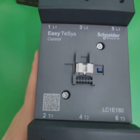
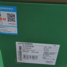
Schneider LC1E180M5N è un Contattore CA appartenente alla serie TeSys E, progettato principalmente per il controllo di carichi elettrici come i motori.
Informazioni di base
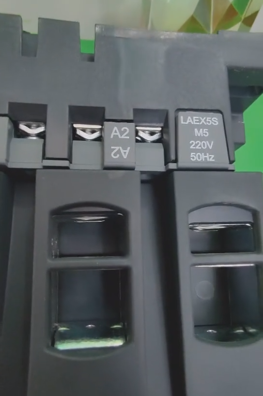
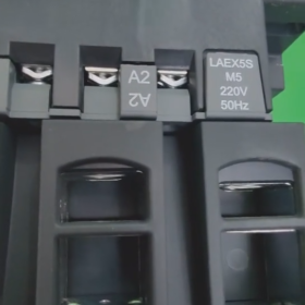
Interpretazione del modello: LC1 designa un contattore; E rappresenta la serie TeSys E; 180 indica la corrente nominale; M significa che la tensione della bobina di controllo è 220 V CA; 5 denota la frequenza della bobina di 50Hz; N significa che il prodotto è conforme agli standard cinesi.
Marca: Schneider
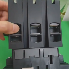
Numero di poli: 3P
Contatti principali: 3NO (Tre normalmente aperti)
Parametri tecnici
Corrente operativa nominale: 18UN (Categoria di servizio AC-3)
Tensione operativa nominale: ≤690 V CA (50/60Hz)
Tensione della bobina di controllo: 220V e
Frequenza della bobina: 50Hz
Vita elettrica: Lunga durata elettrica nella categoria di servizio AC-3
Vita meccanica: Fino a 10 milioni di operazioni
Metodo di montaggio: Supporta il montaggio su guida DIN e il montaggio su piastra di base
Classe di protezione: IP20, impedendo il contatto diretto con le dita
Caratteristiche del prodotto
Lunga durata: Vanta una durata meccanica fino a 10 milioni di operazioni e una vita elettrica elevata, riducendo la frequenza di sostituzione.
Forte adattabilità: Trattato con “TH” protezione, consentendo il funzionamento in ambienti umidi e caldi.
Ampia tolleranza di tensione: La tensione di controllo della bobina può variare entro l'intervallo di 85%-110% Uc senza compromettere il normale funzionamento del prodotto.
Alta versatilità: Dotato di bobina universale compatibile con frequenze 50Hz-60Hz.
Design modulare: Blocchi di contatti ausiliari, blocchi di contatti con ritardo all'attivazione/disattivazione, è possibile collegare all'unità principale interblocchi meccanici e altri moduli. Può anche essere facilmente assemblato in contattori reversibili e avviatori stella-triangolo.
Campi di applicazione
Adatto per carichi AC con fattore di potenza ≥ 0,95. Può essere utilizzato per costruire e rompere motori a gabbia di scoiattolo normalmente avviati, nonché controllare carichi elettrici come le apparecchiature di fabbrica, riscaldatori elettrici, macchine utensili e varie unità di potenza.
Guida all'installazione del contattore Schneider LC1E180M5N
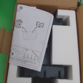
- Preparazione pre-installazione
- Controlla le specifiche del prodotto
Verificare il modello: LC1E180M5N (Serie TeSys E, corrente nominale 180A, tensione bobina 220V AC, 50Hz)
Ispezionare l'aspetto per verificare che non vi siano danni e assicurarsi che lo scivolo dell'arco sia intatto
Confermare che l'ambiente sia asciutto, ben ventilato, esente da gas corrosivi, con un intervallo di temperatura ambiente compreso tra -5 ℃ ~ + 40 ℃
- Preparare strumenti e materiali
Strumenti isolati (tester di tensione, guanti isolanti)
Cacciaviti (viti terminali corrispondenti)
Chiave dinamometrica (intervallo di coppia consigliato: 4-6N·m)
Cavi (circuito principale: 10-50mm²; circuito di controllo: 1-2.5mm²)
Terminali dei cavi
Binario di montaggio (35norma DIN mm) o piastra di montaggio
- Precauzioni di sicurezza
PERICOLO! Rischio di scossa elettrica, esplosione o arco elettrico
Tutte le alimentazioni devono essere scollegate, bloccati e contrassegnati in conformità con la LOTO (Blocco/Tagout) procedura prima dell'installazione, cablaggio o messa in servizio
– Verificare l'assenza di tensione con un dispositivo di rilevamento della tensione prima dell'uso; non fare mai affidamento esclusivamente sui display dello strumento
– Le operazioni di installazione devono essere eseguite solo da personale elettrico qualificato
– Indossare DPI adeguati (Dispositivi di protezione individuale) compresi guanti isolanti e occhiali di sicurezza
– Non aprire lo scivolo dell'arco né toccare parti sotto tensione mentre il contattore è in funzione
III. Passaggi di installazione
- Fissaggio contattore
Montaggio su guida DIN:
- Allineare i fermagli della guida sul retro del contattore con la guida DIN da 35 mm
- Premere con decisione fino a quando a “clic” si sente il suono, indicando che il contattore è bloccato in posizione
- Per rimuovere, fare leva delicatamente sulle clip con un cacciavite per rilasciare il contattore
Montaggio su piastra di base:
- Fissare il contattore utilizzando 4 Viti M6 attraverso i fori di montaggio nella parte inferiore dell'unità
- Assicurarsi che la superficie di montaggio sia piana e che il contattore sia installato verticalmente (angolo di inclinazione <5°) per facilitare la dissipazione del calore
- Cablaggio del circuito principale (Sistema trifase)
| Marcatura del terminale | Contenuto della connessione | Descrizione |
| L1/L2/L3 | Ingresso alimentazione trifase | Collegare al terminale di uscita dell'interruttore o del fusibile |
| T1/T2/T3 | Carica l'uscita (per esempio. motore) | Collegare al motore o ad altri carichi elettrici |
Passaggi operativi:
- Spellare lo strato isolante del cavo per una lunghezza di circa 10-15 mm
- Installare i terminali dei cavi appropriati e crimparli saldamente
- Inserire i terminali dei cavi nei fori dei terminali corrispondenti e serrare le viti alla coppia specificata (4-6N·m)
- Si consiglia di utilizzare separatori di fase per migliorare l'isolamento fase-fase, soprattutto per applicazioni ad alta corrente
- Cablaggio del circuito di controllo
| Marcatura del terminale | Contenuto della connessione | Descrizione |
| A1 | Controllare il cavo sotto tensione dell'alimentazione (l) | Collegare al segnale di avvio del circuito di controllo |
| A2 | Controllare il filo neutro dell'alimentazione (N) | Collegare al terminale comune del circuito di controllo |
| Contatti ausiliari (13-14/21-22) | Feedback o interblocco del segnale | Opzionale, utilizzato per l'indicazione dello stato o il controllo dell'interblocco |
Collegamento tipico del circuito di controllo (Controllo autobloccante):
- Alimentazione di controllo → Pulsante di arresto (normalmente chiuso) → Pulsante di avvio (normalmente aperto) → Morsetto A1 del contattore
- Morsetto A2 → Filo neutro dell'alimentazione di controllo
- Collegare il contatto ausiliario normalmente aperto del contattore in parallelo al pulsante di avvio (per ottenere l'autobloccaggio)
- Installazione degli accessori (Opzionale)
Blocchi di contatti ausiliari (per esempio. ALTRE serie):
Agganciare il modulo sul lato del contattore finché a “clic” si sente il suono, indicando la corretta installazione
Relè di sovraccarico (Si consiglia la serie LR E):
Montare direttamente sotto il contattore e fissarlo con clip; i cavi di collegamento sono precablati internamente
- Messa in servizio e collaudo
- Ispezione del cablaggio
Confermare che tutte le connessioni siano salde, senza allentamenti o cortocircuiti
Verificare che la coppia della vite del terminale soddisfi i requisiti
Verificare che la sequenza delle fasi sia corretta (L1-L2-L3 corrispondente al senso di rotazione del motore)
- Prova a vuoto (Senza collegare il carico)
Accendere l'alimentazione di controllo e testare le azioni di chiusura e apertura del contattore
Osservare se la bobina si surriscalda o produce un rumore anomalo
Controllare se i contatti ausiliari funzionano correttamente (se necessario misurare con un multimetro)
- Prova di carico
Assicurarsi che l'alimentazione del circuito principale sia scollegata ed eseguire prima un test di avanzamento progressivo
Aumentare gradualmente il carico e monitorare l'aumento di temperatura del contattore (non superiore a 60K) e rumore di funzionamento
Testare la funzione di protezione da sovraccarico (se è installato un relè LR E)
- Raccomandazioni per la manutenzione
Ispezione regolare (una volta al mese):
Controllare se i collegamenti dei terminali sono allentati (soprattutto in ambienti vibranti)
Ispezionare le condizioni di usura dei contatti (se sono disponibili indicatori di usura dei contatti)
Controllare se lo scivolo dell'arco è danneggiato
Monitorare eventuali temperature operative anomale
Pulizia e Manutenzione:
Scollegare l'alimentazione prima di pulire la polvere; non utilizzare solventi per pulire i circuiti interni
Assicurarsi che i canali di ventilazione non siano ostruiti
- Risoluzione dei problemi
| Problema | Possibili cause | Soluzioni |
| Il contattore non si chiude | Nessuna tensione/tensione insufficiente sulla bobina | Controllare l'alimentazione di controllo e i collegamenti del circuito |
| Danni alla bobina | Sostituire il contattore | |
| Rumore di funzionamento eccessivo | Superfici di contatto con nucleo in ferro contaminate/ossidate | Pulire le superfici di contatto del nucleo in ferro |
| Tensione di alimentazione instabile | Controllare la qualità dell'alimentazione | |
| Surriscaldamento dei contatti | Contatto scarso | Stringere nuovamente i terminali (prestare attenzione alla coppia specificata) |
| Corrente di carico eccessiva | Controllare se il carico supera il valore nominale |
VII. Riepilogo
La chiave per la corretta installazione del contattore LC1E180M5N risiede: spegnimento sicuro, corretto fissaggio, cablaggio sicuro e test completi. Seguire questa guida non solo garantisce il funzionamento affidabile dell'apparecchiatura, ma ne prolunga anche la durata. Dopo l'installazione, si prega di conservare l'etichetta del prodotto e i registri di installazione per future manutenzioni e ispezioni.
Nota: Questa guida si applica al contattore Schneider LC1E180M5N e ad altri modelli della stessa serie (LC1E120-LC1E630).


")
NH42-63-318x560.png "Commutatori automatici di tipo PC CHINT (ATS)NH42-63/4SZ")


