 Contattore,interruttore automatico,sensore,Codificatore,PLC,Convertitore

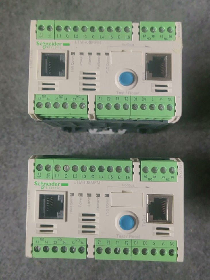

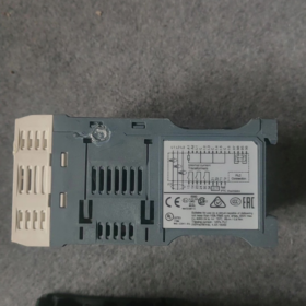
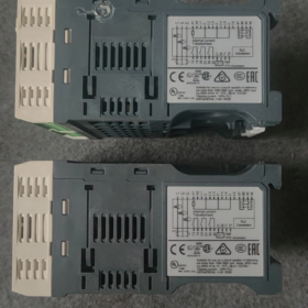
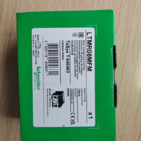
Schneider TeSys‑T (Serie LTMR) Controller di gestione del motore: scenari applicativi
TeSys‑T è una protezione motore intelligente & unità di monitoraggio. Valori fondamentali: protezione completa del motore + Controllo logico I/O + Bus Modbus RTU per dati motore & caricamento del registro degli errori. Si rivolge ai motori asincroni trifase che richiedono una protezione a grana fine, monitoraggio remoto e manutenzione predittiva. Per l'avvio/arresto del motore è necessario un contattore esterno.
Stato del prodotto: Obsoleto pianificato, Data di fine vita: Settembre 30, 2026
Serie: Unità di gestione motore intelligente TeSys‑T, Comunicazione Modbus‑RS485, 0.4-Protezione del circuito motore da 8 A & monitoraggio
- Scomposizione del codice modello
| Campo | Codice | Descrizione |
| LTM | LTM | Serie di sistemi di gestione motore TeSys‑T |
| R | R | Corpo del controllore |
| 8 | 8 | Campo di misurazione della corrente nominale 0,4‑8 A |
| M | M | Comunicazione: ModBus RTU (RS485) |
| F | F | Controllare l'offerta: 100‑240 V CA |
| M | M | Versione terminale M (terminali standard, 6DI / 3DO uscite relè) |
- Elettrico principale & Specifiche dell'hardware
| Articolo | Valore |
| Campo di misurazione della corrente del motore | 0.4 …8A |
| Controllare la tensione di alimentazione | 100‑240 V CA; tolleranza operativa: 93.5~264 V CA, 50/60 Hz |
| Ingressi logici (DI) | 6Ingressi logici di tipo CA a canale; 0-40 V = stato SPENTO, 79-264 V = stato ON |
| Uscite relè (FARE) | 3NO + 1Relè di guasto NO+1NC; valutazione dei contatti: CA 250 V/5 A; CC 30 V/5 A |
| Interfaccia di comunicazione | Modbus‑RTU RS485; doppio RJ45 + porta della morsettiera; velocità di trasmissione:1.2~19,2 kbit/s; intervallo di indirizzi:1‑247 |
| Dimensione complessiva (A×L×P) | 61 × 91 ×122,5 mm; peso:0.53 kg; Montaggio su guida DIN |
| Temperatura ambiente operativa | -20 ℃...+60℃; temperatura di conservazione:-40℃~+85℃; vietata la formazione di condensa |
| Tensione nominale di isolamento Ui | 690 V; grado di inquinamento3, categoria di sovratensioneIII |
| Coppia di cablaggio | 0.5‑0,6 N·m; calibro del filo:0.2‑2,5 mm² solido / cavo flessibile |
III. Funzioni di protezione integrate
Protezione da sovraccarico termico a lungo termine, protezione del rotore bloccato, perdita di fase, squilibrio di fase, inversione di fase, protezione differenziale
Dati registrabili: eventi di guasto, corrente di avviamento, contatore delle ore di funzionamento, contesto di viaggio, capacità termica residua; preallarme supportato
Espansione: con modulo di espansione LTME per la misura della tensione, protezione dal fattore di potenza e dalle variazioni di carico
- Principio di funzionamento approfondito
- Acquisizione attuale: Trifase integrato i trasformatori di corrente misurano il motore corrente efficace reale; rilevamento integrato della corrente di guasto a terra.
- Modello termico: L'algoritmo di memoria termica del motore integrato simula l'aumento della temperatura del motore per la protezione da sovraccarico; ritardo di raffreddamento applicato dopo lo sgancio.
- Logica I/O: 6 I DI ricevono avvio/arresto esterno / comandi locali-remoti; 3 le uscite relè azionano le bobine dei contattori; il relè di guasto fornisce il segnale di allarme.
- busModbus: Carica corrente, stato termico, codici di errore, stato operativo; ricevere comandi di avvio-arresto da remoto e di modifica dei parametri.
- Pulsante locale TEST/RESET blu: ripristino manuale dei guasti & prova locale; Indicatori LED del pannello anteriore (ENERGIA / CORRERE / ALLARME / COLPA).
Nota: Questa unità esegue solo la protezione & controllo logico. Il contattore del circuito principale deve essere cablato esternamente per realizzare un circuito completo di avviamento del motore.
- Definizioni principali dei terminali (Riepilogo)
A1/A2: Alimentazione del controllore, 100‑240 VCA
C1‑C6: 6 canali di ingresso logico (DI)
21-24, 31‑34: 3 NESSUNA uscita relè (per il pilotaggio dei contattori)
95‑96‑97: Relè di guasto, 1NA+1NC
ModBus: RS485 a doppia porta (RJ45 + morsettiera), supporta la rete a margherita
- Aggiornamento & Soluzione sostitutiva (Serie ufficiale TeSys‑Tera di nuova generazione)
TeSys‑Tera adotta un'architettura separata: corpo controllore + sensori CT esterni. La sostituzione diretta dell'hardware pin-to-pin con il vecchio LTMR non è fattibile; è necessaria la modifica del cablaggio del rilevamento della corrente.
| Schema | Unità principale | Sensore di corrente | Intervallo di corrente applicabile |
| Schema1 | LTMTMFM (ModBus, 100‑240 VCA/CC) | LTMTCTV3UT | 0.3-3A |
| Schema2 | LTMTMFM (ModBus, 100‑240 VCA/CC) | LTMTCTV25UT | 2.5-25A |
⚠ Rischi di aggiornamento:
- Il vecchio LTMR integra la TC interna; la nuova Tera utilizza la TC esterna, è necessaria la modifica del cablaggio dell'armadio.
- Mappatura dei registri Modbus & i parametri non sono completamente compatibili; Modifica del programma PLC & la messa in servizio è obbligatoria.
- Il layout dei terminali I/O è completamente diverso; il cablaggio secondario all'interno del quadro elettrico deve essere rielaborato.
VII. Scenari applicativi tipici
Motori asincroni trifase come le pompe, tifosi, compressori e trasportatori; trattamento dell'acqua, metallurgia, petrolio-gas, chimico, industrie del cemento; circuiti motore critici che richiedono accesso al bus basato su PLC per lo stato di protezione del motore e la lettura del registro guasti.
VIII. Note sulla selezione & Condizioni al contorno
- Corrente di misura massima 8A; non applicabile per motori con corrente nominale superiore a 8A.
- I DI sono ingressi di tensione CA, ingressi non a contatto pulito; per la chiusura del contatto è necessaria una tensione di alimentazione esterna.
- Frequenza di commutazione massima dell'uscita relè: 2 Hz; inadatto per applicazioni ciclistiche ad alta frequenza.
- La protezione a livello di armadio è necessaria per ambienti soggetti a condensa o corrosivi.
- Fine vita pianificata: 30 settembre 2026; le progettazioni di nuovi progetti adotteranno preferibilmente TeSys‑Tera.
- Attrezzature industriali di processo generale (Più comune)
- Fan & Circuiti della pompa
Pompe di circolazione, pompe di raffreddamento, pompe per fognature, pompe dell'acqua di reintegro, ventilatori per l'estrazione dei fumi, ventilatori di mandata e ritorno, ventilatori della torre di raffreddamento.
Valori: sovraccarico, rotore bloccato, perdita di fase & protezione da guasto a terra; caricare corrente corrente, stato di errore e tempo di esecuzione; protezione da sottocarico per prevenire il funzionamento a secco della pompa.
Industrie: HVAC, trattamento delle acque reflue, opere idrauliche, edificio MEP.
- Trasportatori, alimentatori a nastro & alimentatori a coclea
Trasportatori a nastro, trasportatori raschianti, alimentatori a coclea, elevatori a tazze.
Valori: viaggio veloce in caso di blocco meccanico; squilibrio di fase & protezione da guasto a terra; cronologia dei guasti per l'analisi degli incidenti di inceppamento; supporto della logica di interblocco.
Industrie: minerario, materiali da costruzione, deposito del grano, gestione logistica, lavorazione chimica.
- Compressori & unità di refrigerazione
Compressori d'aria a vite, compressori frigoriferi, compressori di processo.
Valori: prevenire il bloccaggio del rotore / sovraccarico causato da colpi di liquido; protezione dell'avvolgimento del modello termico; caricare lo stato del motore sul PLC / SCADA tramite bus di campo.
- Trattamento dell'acqua & Industria municipale (Distribuzione di TeSys‑T in grandi volumi)
Pompe di sollevamento, pompe di ritorno, motori agitatori per dosaggio prodotti chimici, ventilatori di aerazione, schermi a barra, raschiatori.
Caratteristiche del sito: grande quantità di motori geograficamente distribuiti; monitoraggio remoto della corrente & guasti per ridurre le ispezioni in loco; elevata incidenza di perdita di fase & guasti a terra.
Architettura tipica: Rete multidrop Modbus‑RTU con PLC, aggregazione dei dati di protezione del motore all'host SCADA.
- Chimico & Industria farmaceutica
Agitatori del reattore, pompe di circolazione, pompe dosatrici, pompe di trasferimento materiale, centrifughe.
Valori:
- Protezione differenziale che riduce i danni al motore dovuti alle perdite dei fluidi di processo.
- Registro completo degli eventi di guasto per la tracciabilità del processo e la conformità GMP.
- Protezione dall'inversione di fase per impedire la rotazione inversa dopo lo scambio di fase di manutenzione.
Nota: Il corpo del controller non può essere installato direttamente in aree pericolose esplosive; custodie antideflagranti / sono necessari contattori.
- Metallurgia, Cemento & Materiali da costruzione
Ventole per la rimozione della polvere, ventole di raffreddamento, attuatori di distribuzione, scarico delle unità, piccoli motori per rulliere.
Condizioni operative: carichi d'urti pesanti, polvere elevata; frequente rotore bloccato & eventi di perdita di fase; sovraccarico termico combinato & Lo scatto rapido a rotore bloccato protegge gli avvolgimenti del motore.
- Azionamenti ausiliari per centrali elettriche
Piccoli motori ausiliari: ventole di raffreddamento, pompe dell'olio lubrificante, pompe dell'acqua di tenuta.
Valori: apparecchiature ausiliarie critiche; preallarme & registrazione delle istantanee dei guasti per l'analisi delle cause principali dopo gli incidenti.
- Imballaggio logistico & Macchinari per la plastica
Nastri trasportatori, agitatori, alimentatori, azionamenti ausiliari per piccoli estrusori.
Vantaggi: locale / selezione della modalità remota tramite DI; Il pilotaggio della bobina del contattore tramite DO elimina numerosi relè intermedi.
✅ Criteri di selezione per TeSys‑T
Scegli LTMR se si applica una delle condizioni seguenti:
- È richiesta la comunicazione tramite bus di campo: leggi corrente, percentuale di capacità termica, orari di funzionamento, codici di guasto e istantanee dei guasti.
- Motori preziosi che richiedono una protezione completa: sovraccarico termico, rotore bloccato, perdita di fase, squilibrio di fase, inversione di fase, guasto a terra, sottocarico.
- Modalità di controllo doppio locale-remoto più logica di interblocco complessa; ridurre il conteggio dei relè intermedi.
- Requisito in loco per la registrazione dei guasti per la risoluzione dei problemi post-evento.
- Rete di monitoraggio centralizzato multimotore collegata a PLC / SCADA.
❌ Scenari applicativi non idonei
- È necessaria solo la semplice protezione del relè termico senza comunicazione o registrazione dei guasti: scegli invece i relè di sovraccarico termico LRD a basso costo.
- La corrente a pieno carico del motore supera di gran lunga la gamma del TA integrato (max TC integrato LTMR:100 UN). Utilizzare TeSys‑Tera di nuova generazione con CT esterno per motori a corrente più elevata.
- Ciclo motorio ad alta frequenza: relè DO frequenza di commutazione massima 2Hz; l'usura dei contatti accelererà.
- Zone pericolose a sicurezza intrinseca: il corpo del controller non può essere montato all'interno di un'area pericolosa.
- Protezione motore monofase: TeSys‑T è adatto ai motori a induzione trifase.
📌 Riepilogo della vecchia e della nuova generazione
Eredità: Serie LTMR (per esempio. LTMR08MFM), EOL pianificato dal 30 settembre al 2026, trasformatori di corrente incorporati.
Nuovo: TeSys‑Tera (serie LTMT), architettura TC esterna, copertura attuale più ampia; preferito per l'ingegneria di nuovi progetti.
Principio di protezione da sovraccarico termico di Schneider TeSys‑T (LTMR)
TeSys‑T non si basa sulla deformazione fisica della striscia bimetallica come i relè termici convenzionali. Implementa la protezione da sovraccarico termico tramite modello termico elettronico (Algoritmo della memoria termica del motore virtuale) + campionamento della corrente trifase a vero valore efficace.
- Fase di acquisizione dell'hardware
- I trasformatori di corrente trifase integrati campionano la vera corrente efficace dello statore (non semplici valori di picco).
- Circuito di rilevamento della corrente di guasto a terra integrato.
- I segnali di corrente analogica vengono digitalizzati dall'MCU per l'aggiornamento periodico della corrente di carico.
Per LTMR08MFM: campo di misura CT interno:0.4‑8 A per la misurazione diretta della corrente del circuito statorico.
- Nucleo: Modello termico del motore virtuale (Memoria termica)
Il controller esegue un modello matematico che simula l'accumulo di calore nell'avvolgimento del motore e la dissipazione del calore:
theta_{virtuale} \propto \int(I^2 \cdot t)dt
Accumulo di calore: La percentuale di capacità termica aumenta quando la corrente operativa supera la corrente nominale del motore.
Dissipazione del calore: La percentuale di capacità termica diminuisce durante l'arresto o il funzionamento a carico leggero, simulando il raffreddamento naturale del motore.
Due parametri chiave configurabili determinano il comportamento del modello:
- Corrente nominale del motore I: impostato in base alla corrente a pieno carico della targa del motore.
- Classe di viaggio (5/10/15/20/30), definisce le caratteristiche di intervento a tempo inverso.
📌 Percentuale di capacità termica: variabile interna 0‑100%; l'intervento per sovraccarico si attiva al 100%. Questo valore può essere letto tramite il registro Modbus.
Definizione di classe di viaggio
| Classe di viaggio | Tempo di viaggio @7,2×Ir | Applicazione tipica del motore |
| Classe5 | 4-5 secondi | Motori ad avviamento rapido |
| Classe10 | 6-10 secondi | Motori a induzione trifase standard per uso generale (più utilizzato) |
| Classe15 | 9-15 secondi | Applicazioni con carico iniziale gravoso |
| Classe20 | 12-20 secondi | Motori ad avviamento pesante a inerzia elevata |
| Classe30 | 18-30 anni | Carichi ad alta inerzia con tempi di avviamento prolungati (per esempio. grandi tifosi) |
- Gestione del sovraccarico per due condizioni operative tipiche
① Sovraccarico di funzionamento continuo (sovracorrente persistente)
Il motore funziona continuamente con I>Ir; la capacità termica virtuale si accumula fino a raggiungere il 100%. Il controller emette il comando di sgancio, diseccita le uscite relè della bobina del contattore e arresta il motore. Codice di errore di sovraccarico più istantanea del guasto (3-corrente di fase & capacità termica all'istante di intervento) vengono memorizzati.
② Sovraccarico durante l'avviamento del motore (corrente di spunto iniziale di elevata entità)
La Trip‑Class configurata consente un'elevata corrente di avviamento a breve termine senza sganci fastidiosi; il modello termico dissipa il calore accumulato una volta completato l'avvio.
⚠ Caratteristica critica: Conservazione della memoria termica
Dopo lo sgancio per sovraccarico, Il valore della capacità termica virtuale non si ripristina immediatamente anche se l'alimentazione del controller rimane attiva. Deve trascorrere il tempo di raffreddamento simulato nel modello oppure è necessario il RESET manuale.
Caso pratico: dopo che il motore è scattato per sovraccarico, gli avvolgimenti rimangono caldi. Ripristino istantaneo & il riavvio rischia di bruciare il motore. La memoria termica previene il riavvio prematuro e imita il comportamento di raffreddamento del motore reale.
- Funzione di preallarme (Avviso precoce di sovraccarico)
Soglia di capacità termica configurabile (per esempio. 80%). Quando la capacità termica virtuale supera la soglia, il preallarme di sovraccarico si attiva senza intervento. Il segnale di avviso può essere trasmesso tramite relè DO o Modbus per la manutenzione predittiva prima dell'arresto non pianificato.
- Confronto: Relè termico bimetallico convenzionale e modello termico elettronico TeSys‑T LTMR
| Articolo | Relè termico bimetallico tradizionale LRD | Protezione da sovraccarico modello termico elettronico TeSys‑T LTMR |
| Principio di protezione | Deformazione termica fisica della striscia bimetallica | Modello termico virtuale basato su software con campionamento della corrente RMS |
| Caratteristica della memoria termica | Il calore svanisce in caso di perdita di potenza; nessuna ritenzione termica | La memoria termica può essere conservata in caso di interruzione dell'alimentazione (configurabile) |
| Influenza della temperatura ambiente | Forte dipendenza dalla temperatura del cabinet, deviazione notevole | Compensazione della temperatura del software; bassa sensibilità alla temperatura ambientale |
| Impostazione della classe di viaggio | Fisso (i modelli limitati supportano la regolazione) | Classe 5‑30 configurabile tramite software |
| Disponibilità dei dati | Nessuna uscita di stato | Capacità termica leggibile dal bus, istantanee dei guasti, misurazioni attuali |
- Condizioni al contorno & Limitazioni
- La protezione da sovraccarico protegge l'accumulo termico dell'avvolgimento del motore, non cavi di alimentazione; è necessario un interruttore separato per la protezione dei conduttori del cavo.
- Perdita di fase / lo squilibrio di fase accelera l'accumulo del modello termico e fa avanzare la soglia di intervento.
- Il rotore bloccato e il guasto a terra sono funzioni di protezione indipendenti, non fa parte della logica di sovraccarico.
- Regolare la Trip‑Class se le condizioni effettive di raffreddamento del motore si discostano dal modello interno (per esempio. motore raffreddato ad aria forzata).
- Il modello termico LTMR è progettato per motori a induzione trifase standard. Il riutilizzo diretto per motori alimentati da VFD o per scopi speciali non è valido; la regolazione dei parametri è obbligatoria.
- Logica di ripristino degli errori
- Ripristino automatico: abilitato per i parametri; il ripristino avviene solo dopo che il modello termico si è raffreddato fino a raggiungere un livello di capacità termica sicuro.
- Ripristino manuale: pulsante RESET locale del pannello frontale, Segnale di ripristino del terminale IN, o comando di ripristino del bus Modbus.
Operazione vietata: ripetuti riavvii forzati prima che il motore si raffreddi dopo lo sgancio termico.
- Codice errore
Codice di errore intervento per sovraccarico termico: Olimpiadi1. Il registro dei guasti memorizza il timestamp, percentuale di corrente trifase e capacità termica, recuperabile tramite Modbus.



NH42-63-318x560.png "Commutatori automatici di tipo PC CHINT (ATS)NH42-63/4SZ")



