 Contattore,interruttore automatico,sensore,Codificatore,PLC,Convertitore

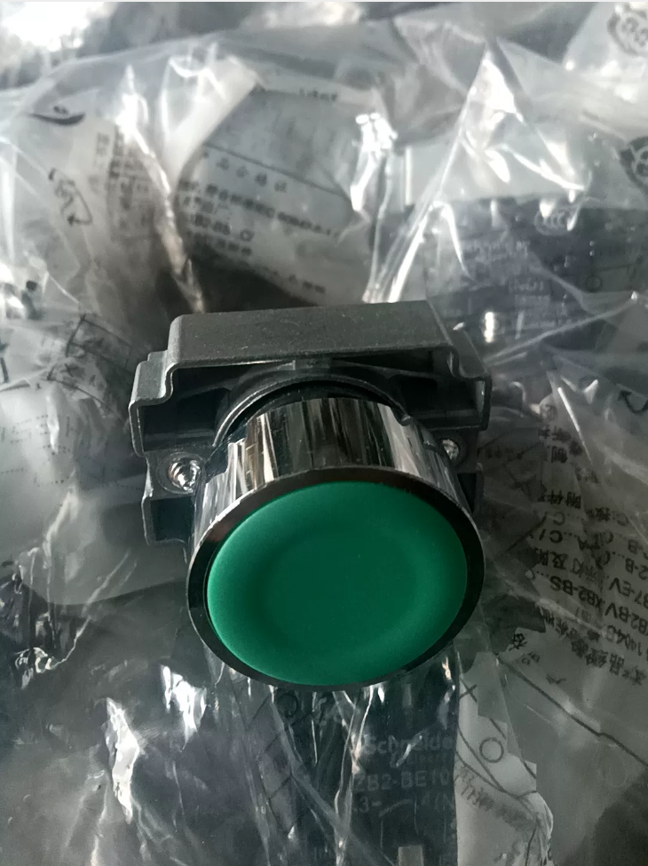

Spiegazione del modello
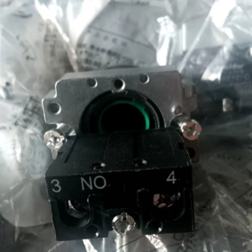
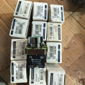
XB2-BA31C (Modello di ordinazione completo; suffisso “C” non può essere omesso)
XB2: Armonia XB2, 22 mm serie di pulsanti in metallo
BA: Testa a filo, pulsante con ritorno a molla
3: Verde
1: 1 Contatto normalmente aperto (1NO)
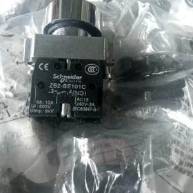
Ripartizione dei componenti: ZB2BA3C (testa del pulsante) + ZB2BZ101C (1NO blocco contatti)
- Principali Specifiche Tecniche
| Articolo | Parametro |
| Diametro del ritaglio di montaggio | Foro pannello standard Φ22 mm |
| Tipo di operazione | Ritorno primaverile (momentaneo, rimbalza automaticamente al rilascio) |
| Colore del pulsante | Verde (pulsante di avvio standard) |
| Configurazione dei contatti | 1NO (Normalmente aperto, terminali 3-4) |
| Materiale della lunetta | Metallo cromato, resistente agli urti |
| Grado di protezione | IP65 (lato del pannello frontale) |
| Corrente termica nominale | 10 UN, tensione nominale di isolamento Ui = 600 V |
| Resistenza meccanica | ≥ 3 milioni di operazioni |
| Temperatura operativa | -25 ℃ ~ +55 ℃ |
| Tipo di cablaggio | Collegamento con terminale a vite |
- Applicazioni tipiche
Pulsante di avvio per quadri elettrici industriali: avviamento del motore, attivazione del funzionamento dell'apparecchiatura, circuiti di controllo jog.
Riferimento corrispondente: Pulsante di arresto rosso XB2-BA42C (1NC)
- Pulsanti da incasso comuni della stessa serie
XB2-BA11C: Bianco, 1NO
XB2-BA21C: Nero, 1NO
XB2-BA31C: Verde, 1NO (questo modello)
XB2-BA41C: Rosso, 1NO; XB2-BA42C: Rosso, 1NC
XB2-BA51C: Giallo, 1NO
XB2-BA61C: Blu, 1NO
- Note di installazione
- Spessore pannello applicabile: 1~6 mm
- Coppia di serraggio consigliata per il dado di montaggio: 0.8 N·m
- Per ulteriori contatti, impilare ZB2-BE101 (NO) / ZB2-BE102 (NC) moduli di contatto
- Questo modello non è dotato di indicatore luminoso integrato; per pulsante di avvio illuminato di colore verde, selezionare la serie XB2BW33C
Procedura di installazione completa per Schneider XB2-BA31C (XB2-BA31)
Composizione dei componenti: ZB2BA3C (testa del pulsante a filo verde) + ZB2BZ101C (1NO blocco contatti)
Precondizioni & Utensili
- Requisiti del pannello
Ritaglio standard: Φ22 mm, ritaglio sbavato senza spigoli vivi
Spessore pannello applicabile: 1~6 mm
Distanza minima dal centro tra i pulsanti adiacenti: ≥ 30 mm
- Strumenti richiesti
Cacciavite piatto (PH1), spelafili; consigliato cacciavite dinamometrico
- Valori di coppia standard ufficiali
Dado di montaggio del pulsante: 0.8 N·m (NON stringere eccessivamente)
Viti terminali: 0.5~0,8 N·m
- Specifiche del cavo
Cavo di controllo in rame intrecciato consigliato da 0,5~1,5 mm², lunghezza di spelatura 7~10 mm
Sequenza di installazione standard passo dopo passo
⚠️ Primo passo per tutti i lavori elettrici: Interrompere l'alimentazione principale del quadro elettrico, implementare il blocco & tagout!
Fare un passo 1: Inventario delle parti & Ispezione visiva
Controllare il set completo dopo aver disimballato:
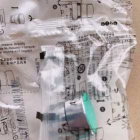
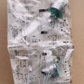
- Testa operativa a pulsante verde ZB2BA3C (dotato di guarnizione di tenuta per garantire la protezione IP65)
- Dado di bloccaggio in metallo
- Blocco contatti ZB2BZ101C (1NO)
Verificare che la guarnizione di tenuta sia intatta e che i fermi in plastica siano esenti da crepe.
Fare un passo 2: Inserire la testa del pulsante nel pannello di controllo (Installare dalla parte FRONTE del pannello)
- Montare correttamente la guarnizione di tenuta sulla spalla posteriore della testa del pulsante (la guarnizione non può essere omessa o attorcigliata)
- Inserire la testa del pulsante nel ritaglio Φ22 mm dall'esterno (anteriore) lato del pannello
- Il gambo filettato si estende dal pannello posteriore; mantenere la testa del pulsante strettamente attaccata alla superficie del pannello senza inclinarla
Fare un passo 3: Montare il dado di bloccaggio per fissare la testa del pulsante
- Avvitare il dado di bloccaggio in metallo sul gambo filettato dal lato posteriore, serrare a mano fino a toccare il pannello
- Stringere uniformemente con lo strumento, mantenere la coppia a 0.8 N·m
✅Criteri di accettazione: Pulsante privo di oscillazioni, pressatura dolce senza inceppamenti
❌ Non applicare una forza eccessiva! Un serraggio eccessivo potrebbe rompere la guarnizione di tenuta, causare il grippaggio del pulsante e invalidare la protezione IP65.
Fare un passo 4: Blocco contatti ad innesto (Punto di errore di assemblaggio più frequente)
- Due fermi elastici sul lato anteriore del blocco contatti si allineano con le fessure sul retro della testa del pulsante
- Spingere il blocco contatti orizzontalmente e diritto; due udibili “clic” i suoni confermano il completo inserimento di entrambi i fermi
❗ Non fare leva in diagonale né premere con forza con violenza; i fermi rotti richiedono la sostituzione del blocco contatti
✅ Metodo di rimozione: Fare leva delicatamente su entrambi i fermi laterali con un cacciavite piatto e tirare indietro il blocco contatti
Fare un passo 5: Operazione di cablaggio (XB2-BA31, 1NESSUN contatto)
Marcatura del terminale stampata sul blocco contatti:
Terminali 3, 4 = Normalmente aperto (NO): Circuito aperto a riposo, chiuso quando premuto
- Spellare l'isolamento del cavo, prevenire fili di rame allentati e sbavature
- Inserire il conduttore nel foro del terminale; assicurarsi che l'isolamento non sia bloccato sotto la vite
- Stringere la vite del terminale in senso orario (coppia 0,5~0,8 N·m)
- Test di trazione leggera sul cavo per confermare l'assenza di allentamenti; i fili di rame esposti possono comportare il rischio di cortocircuito
Fare un passo 6: Test meccanico prima dell'accensione (Procedura obbligatoria)
- Premere ripetutamente il pulsante: funzionamento regolare, rimbalzo automatico istantaneo dopo il rilascio, nessun grippaggio o rumore anomalo
- Confermare visivamente che i fermi del blocco contatti siano completamente bloccati per evitare il distacco in caso di vibrazioni
- Controllare che la guarnizione di tenuta si adatti al pannello in modo uniforme e senza spazi vuoti (fondamentale per la polvere & resistenza all'acqua)
Fare un passo 7: Test di continuità prima dell'energizzazione
Utilizzare la modalità di continuità del multimetro per testare i terminali 3 E 4:
Stato di riposo: Circuito aperto (resistenza infinita)
Tenere premuto il pulsante: Conduttivo (resistenza vicina a 0 OH)
Procedere all'accensione solo dopo aver superato il test.
Riferimento di cablaggio tipico (Circuito di avvio standard)
Alimentazione di controllo → Terminale 3
terminale 4 → Bobina del contattore / Ingresso digitale del PLC
Pulsante premuto → Terminali 3-4 condotta, segnale di avvio attivato
Errori comuni di installazione & Avvertenze
- Mancante / guarnizione di tenuta deformata → Perdita del grado di protezione IP65; l'ingresso di polvere e umidità provoca ossidazione da contatto e scarsa conduttività
- Coppia eccessiva sul dado di montaggio → Meccanismo interno compresso, il pulsante non riesce a rimbalzare
- Blocco contatti con forzatura diagonale → Rottura delle chiusure in plastica; il blocco contatti potrebbe staccarsi durante il funzionamento dell'apparecchiatura
- Cavo eccessivamente spelato e fili di rame allentati → Rischio di cortocircuito tra terminali adiacenti
- Ritaglio del pannello più grande di Φ22,2 mm → Il pulsante traballa e la tenuta non funziona
- Non montare prima il blocco contatti e poi passare il pulsante attraverso il pannello! Sequenza corretta: Fissare prima la testa del pulsante al pannello, quindi allegare il blocco contatti
Procedura di smontaggio (Per la manutenzione dei contatti & sostituzione)
Interrompere l'alimentazione → Fare leva sui due fermi del blocco contatti con un cacciavite piatto → Tirare indietro il blocco contatti;
Per rimuovere il pulsante completo: Svitare il dado di bloccaggio posteriore, estrarre la testa del pulsante dal frontale del pannello.
Principio di funzionamento di Schneider XB2-BA31C (XB2-BA31)
Composizione dei componenti: ZB2BA3C (testa del pulsante con ritorno a molla verde) + ZB2BZ101C (1NO blocco contatti)
È un pulsante meccanico momentaneo senza spia.
- Principio di funzionamento meccanico
- Stato iniziale (Non pressato)
La molla di compressione incorporata spinge la testa operativa verso l'esterno e mantiene la posizione estesa. Il contatto mobile interno è separato dal contatto stazionario.
- Stato di attuazione (Premere il pulsante verso il basso)
La forza esterna preme la testa del pulsante verde → L'asta di spinta interna si sposta all'indietro → Fa spostare il ponte di contatti mobile all'interno del blocco di contatti
Il ponte di contatto collega due contatti fissi contemporaneamente, terminali 3 E 4 (NO) Chiuso.
- Stato di rilascio (Ritorno automatico)
Quando la pressione esterna scompare, la molla integrata rimbalza e ripristina l'asta di spinta; il ponte di contatto si ritrae, i contatti si separano di nuovo, circuito tra 3 E 4 si apre.
Caratteristica: Tipo momentaneo (funzionamento a scatti), senza bloccaggio; conduttivo solo mentre viene premuto.
- Principio elettrico (XB2-BA31: 1NONormalmente aperto)
Marcatura dei terminali sul blocco contatti: 3, 4 = Normalmente aperto (NO)
Stato statico: Circuito aperto tra 3 E 4 (resistenza infinita)
Pulsante: Circuito chiuso tra 3 E 4
Al momento del rilascio: Il circuito ripristina immediatamente lo stato aperto
I contatti sono contatti puliti meccanici passivi:
Nessun alimentatore integrato; accende/spegne solo i circuiti di controllo esterni. Compatibile con loop di controllo AC/DC a bassa tensione (bobine del contattore, Ingressi DI del PLC, circuiti relè).
- Breve ripartizione della struttura interna
- Alloggiamento del pulsante + ritorno a molla
- Asta di trasmissione (trasmettere la forza di pressione)
- Blocco contatti: Contatti stazionari fissi + ponte di contatti conduttivo mobile
- Terminali di cablaggio a vite
Sequenza di trasmissione della forza:
Pressione manuale → Testa del pulsante → L'asta comprime la molla → Spostamento del ponte di contatto → Contatti chiusi
Pulsante di rilascio → La molla si estende e si ripristina → Il ponte di contatto si ritira → I contatti si aprono
- Caratteristiche chiave
- Nessuna spia incorporata, non è necessaria alcuna alimentazione elettrica per l'illuminazione; distinguerlo dal modello illuminato XB2BW33C.
- Commutazione di contatti puramente fisici e meccanici senza componenti elettronici, forti prestazioni anti-interferenza.
- La protezione IP65 si basa sulla guarnizione di tenuta anteriore per impedire l'ingresso di vapore acqueo e polvere nella cavità di contatto.
- Logica applicativa tipica (Esempio di circuito di avvio del motore)
Controlla live L → Terminale 3
terminale 4 → Bobina KM contattore → Neutro N
Quando si preme XB2-BA31C → la bobina KM si eccita, il contattore si inserisce;
Il circuito del pulsante si apre al rilascio, funzionamento continuo mantenuto mediante autobloccaggio tramite contatto ausiliario NA del contattore.
Malintesi comuni
❌ Non è un pulsante ad aggancio: Il circuito si apre dopo il rilascio, non può sostenere lo stato di conduzione
❌ Non adatto come finecorsa in compressione continua; accelera l'affaticamento primaverile
❌ I contatti servono solo circuiti di controllo, non possono pilotare direttamente carichi ad alta potenza





NH42-63-318x560.png "Commutatori automatici di tipo PC CHINT (ATS)NH42-63/4SZ")



