 コンタクタ,サーキットブレーカー,センサー,エンコーダ,PLC,コンバータ

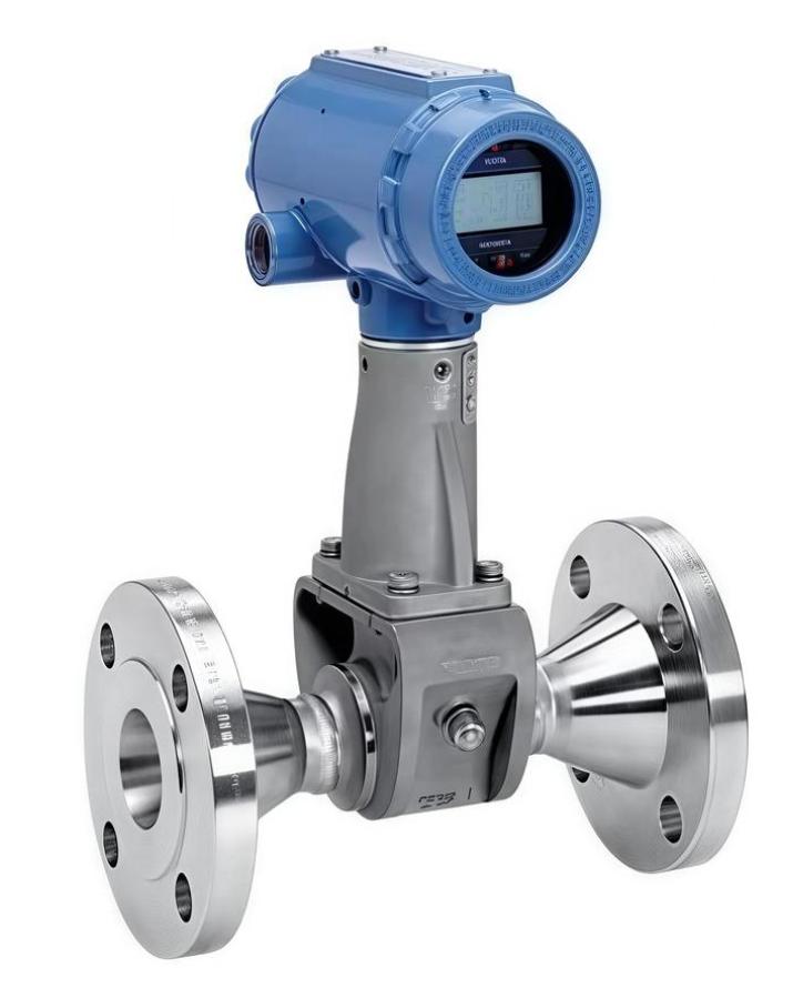
モデルの完全な番号: 8800DF010SA1N1D1K8M5Q4
製品: Emerson Rosemount Model 8800D Flanged Vortex Flowmeter
Applicable fluids: 液体, ガス, 飽和蒸気と過熱蒸気.
Step-by-Step Model Code Decoding
`8800D F 010 S A1 N 1 D 1 K8 M5 Q4`
- 8800D: 製品シリーズ, vortex flowmeter body
- F: Flanged connection style (W = Wafer style)
- 010: 呼び径 1 インチ / DN25
- S: Wetted material: 316/316Lステンレス (CF3M cast stainless steel)
- A1: フランジ規格: ASME B16.5 RF Class150 (ANSI Class 150 raised-face flange)
- N: Standard temperature version: -40℃ ~ +232℃
- 1: ハウジング材質: Aluminum housing with 2 × 1/2-14 NPT cable entries
- D1: Electronics module: 4–20mA + HART analog output, no pulse output
- K8: Explosion-proof certification: Chinese certification (Exd flameproof + Exia intrinsically safe, CNEX certified)
- M5: Transmitter head: Local LCD digital display
- Q4: Optional suffix code: SIL2 safety certification + Advanced Process Diagnostics (CriticalProcess)
Summary of Key Specifications
呼び径: DN25 (1″), ANSI Class150 flange
コミュニケーション: 4~20mA + HART7
Equipped with local LCD display
Explosion protection: Dual certification of domestic flameproof and intrinsic safety
SIL2 safety integrity level, suitable for SIS safety loops
Measurable media: Steam, compressed air, water and various process fluids
構造上の利点: All-welded non-gasket anti-clog design; sensor can be replaced online without pipeline depressurization or shutdown
補足情報
- Common base model: 8800DF010SA1N1D1K8M5. The suffix Q4 is an optional add-on for SIL certification and advanced diagnostics.
- Typical industries: Thermal power plants, 化学工業, pharmaceutical manufacturing, HVAC steam metering.
- Replacement reminder: When selecting replacement units, nominal diameter, flange pressure class, explosion-proof grade and SIL certification must be fully matched.
Installation Dimensions – Rosemount 8800DF Flanged Type DN25 (1″, Model 8800DF010) ANSI150 RF
Applicable to your model: 8800DF010SA1N1D1K8M5Q4 (DN25 Class150 Flanged Vortex Meter)
> All data sourced from Emerson official document 00813-0106-4004
- Critical Overall Dimensions (ユニット: mm)
| パラメータ | DN25 1″ Class150 RF (8800DF010 A1) | 備考 |
| Face-to-Face dimension (あ) | 165 mm | Core installation dimension (length between flange sealing faces) |
| Flange outer diameter OD | 165 mm | ASME B16.5 Class150 standard 1-inch flange |
| Bolt circle diameter | 120.7 mm | |
| 量 & size of bolt holes | 8 × M16 (5/8″) | |
| Flange thickness | 29.2 mm | |
| Total transmitter height (flange center to top of display) | ≈240~255 mm | Transmitter head rotatable at 0°/90°/180° |
| Cable entry | 2 × 1/2 NPT (housing code 1 as per your configuration) | |
| Maximum outer diameter of meter body | 95 mm | |
| Approximate net weight | ≈7.3 kg | Version with LCD display |
> ⚠️ Important distinction: 8800DW = Wafer type; 8800DF = Flanged type. Their face-to-face lengths differ completely and cannot be interchanged.
- Straight Pipe Requirements (Mandatory for measuring accuracy, D = DN25)
- Upstream, no flow disturbances (straight pipe without valves or elbows): ≥10D (≥250 mm)
- Downstream (universal requirement): ≥5D (≥125 mm)
- Single in-plane 90° elbow upstream: ≥20D
- Two out-of-plane 90° elbows upstream: ≥30D
- Control valves must be installed downstream of the flowmeter. If valves are fitted upstream, upstream straight pipe length ≥50D.
- Installation Orientation Guidelines (Steam / 液体 / Gas service)
- Saturated steam measurement (most common working condition)
Preferred arrangement: Horizontal pipeline, transmitter head mounted horizontally sideways (prevents condensate from flowing into sensor support)
Do NOT mount transmitter head vertically downward
- Liquid service
Horizontal installation recommended. For vertical piping, fluid must flow upward only. Downward flow is prohibited (risk of gas entrapment and incomplete pipe filling)
Avoid installation at pipeline high points (gas accumulation)
- Gas service
Horizontal or upward vertical installation preferred; avoid low points where liquid may collect
- Strict Installation Prohibitions
- Thermal insulation shall not cover the lower section of transmitter support to avoid overheating electronics (maximum ambient temperature: 85℃).
- Flange gaskets must not intrude inward into the pipeline bore during assembly.
- Upstream and downstream piping must be concentric; misalignment shall be less than 0.5 mm.
- Keep away from strong vibration sources such as reciprocating pumps and compressors. If vibration is unavoidable, install pipe supports at 2D upstream and downstream.
- The 8800D body does not come with an integrated flow conditioner. Install a pipeline flow conditioner if sufficient straight pipe cannot be provided.
- Quick Reference for Face-to-Face Length (Flanged Class150) for other sizes
DN15(005): 140 mm
DN25(010): 165 mm (あなたのモデル)
DN40(015): 178 mm
DN50(020): 203 mm

