 コンタクタ,サーキットブレーカー,ソーラーインバーター,電気メーター,太陽電池

Model A9L40600 Schneider – Model Analysis and Technical Parameters
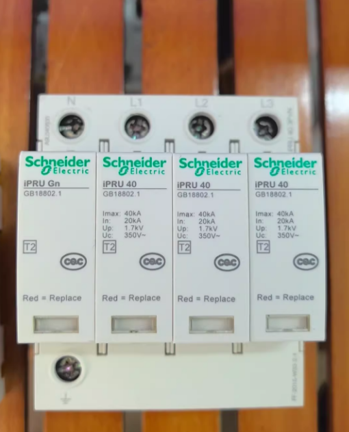
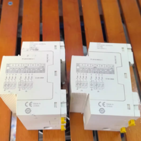
A9L40600 is the complete order number of a low-voltage surge protection product (Surge Arrester) 下 シュナイダーエレクトリック‘s Acti9 Series. It belongs to the iPRD40 modular surge arrester series and is mainly used for Type 2 surge protection in power distribution systems.
- Model Segment Analysis
| コードセグメント | 説明 | Corresponding Product Attribute |
| A9 | Schneider Acti9 Series Identifier | A standardized low-voltage component series for terminal power distribution, including circuit breakers, surge arresters, 等. |
| L40 | Product Type Sub-code | Represents the iPRD40 series modular surge arrester. “L” generally indicates surge protection products, そして “40” corresponds to the 40kA maximum discharge current rating. |
| 600 | Structural Feature and Configuration Code | Corresponding to 3P+N (三相 + 中性) 極構成, 350V定格電圧, and equipped with a pluggable trip module |
- Summary of Core Product Attributes
| アイテム | Specification Parameter |
|---|---|
| Brand and Series | Schneider Acti9 iPRD40 Series |
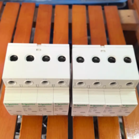
| 製品タイプ | タイプ 2 modular surge arrester (with pluggable trip unit) |
| ポール構成 | 3P+N (三相 + 中性) |
| 定格電圧 (UC) | 350Vと (suitable for domestic 400V three-phase systems) |
| 最大放電電流 (アイマックス) | 40の (8/20μs波形) |
| 保護クラス | タイプ 2 (secondary surge protection for power distribution systems) |
| Technical Principle | Combined technology of MOV (金属酸化物バリスタ) + GDT (ガス排出管) |
| Applicable Earthing System | TN-S, TTシステム (TN-Cには適用されません, ITシステム) |
- Detailed Technical Parameter Table
| パラメータのカテゴリ | 具体的な値 | 備考 |
| 電気的パラメータ | ||
| 定格動作電圧 | 350Vと | 50/60Hz |
| 最大放電電流 | 40の (8/20μs) | Core indicator of surge protection |
| 公称放電電流 | 20の (8/20μs) | |
| 電圧保護レベル (上) | ≤ 1.5kV | Measured at In=10kA |
| 応答時間 | ≤ 25ns | MOV+GDT combined technology ensures fast response |
| Mechanical and Installation Parameters | ||
| Module Width | 4 モジュール (72mm) | Suitable for 35mm DIN standard rail |
| 寸法 | 85mm (H) × 72mm (W) × 69mm (D) | |
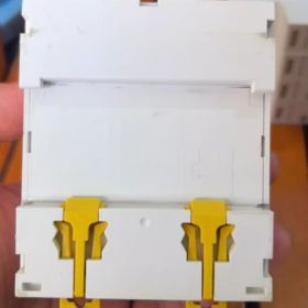
| ターミナル | Suitable for 2.5~35mm² copper conductors | Recommended torque: 8~10N・m |
| 保護クラス | IP20 | Suitable for installation inside power distribution cabinets |
| Environmental and Service Life Parameters | ||
| 動作温度 | -25℃~+60℃ | |
| 保管温度 | -40℃~+85℃ | |
| 機械的寿命 | ≥ 10,000 回 (plug-in operation) | |
| 電気的寿命 | IECに準拠 61643-11 標準 | The pluggable module can be replaced when surge protection components age |
| 認証と規格 | ||
| 準拠規格 | IEC 61643-11, GB 18802.1 | Certified with CE and CCC |
- Core Functions and Working Principle
- Surge Suppression Mechanism: Adopts MOV+GDT hybrid technology. MOV is responsible for fast response (≤25ns) to suppress most surges, while GDT provides higher surge withstand capacity and lower leakage current.
- Fault Indication Function: The pluggable module is equipped with a visual status indicator (緑色 = 通常, 赤 = 故障) for quick identification of protection status.
- サーマルトリップ保護: Built-in thermal trip device automatically trips when surge energy is excessive or components age, preventing overheating damage to the arrester.
- Replaceable Design: Only the pluggable trip module needs to be replaced after a fault, eliminating the need for overall replacement and reducing maintenance costs.
- 典型的なアプリケーションシナリオ
| 応用分野 | Specific Application Scenario | Protection Target |
| 商業ビル | Main/distribution power cabinets in office buildings, ショッピングモール, ホテル | Protect critical loads such as air conditioners, エレベーター, and lighting systems |
| 産業プラント | Production line control circuits, PLCシステム, front-end of frequency converters | Prevent damage to precision electronic equipment caused by lightning strikes or grid fluctuations |
| データセンター | UPS input/output terminals, front-end of server cabinet PDUs | Ensure continuous and stable operation of IT equipment and avoid data loss |
| インフラストラクチャー | Critical power distribution circuits in hospitals and transportation hubs | Protect life-safety related equipment and control systems |
| 太陽光発電システム | AC side output terminals of inverters | Suppress surges generated by photovoltaic systems and grid feedback surges |
- 設置および操作上の注意事項
- 設置場所:
As Type 2 保護, it should be installed in the main or distribution power cabinet, after the main circuit breaker.
Recommended to be installed close to the protected equipment, with the line length not exceeding 10 メートル.
- 配線要件:
Phase lines (L1/L2/L3) and neutral line (N) must be wired correctly according to the markings.
The protective earthing (PE) wire should be as short and thick as possible. It is recommended to use ≥16mm² copper conductors with a length not exceeding 50cm.
All terminals must be tightened to the recommended torque (8~10N・m) to prevent overheating due to poor contact.
- 要件の一致:
A 16A~32A miniature circuit breaker or fuse must be installed upstream as overcurrent protection to prevent short circuits caused by surge arrester faults.
Not applicable to IT and TN-C earthing systems, only suitable for TN-S and TT systems.
- メンテナンスポイント:
Regularly check the status indicator (緑色 = 通常, 赤 = 故障).
Replace the pluggable trip module in a timely manner after a fault; do not perform plug-in operations with power on.
It is recommended to conduct a surge protection performance test every 2 年.
- Reference of Related Models in the Same Series
| モデル | 極数 | 最大放電電流 | 定格電圧 | アプリケーションシナリオ |
| A9L40200 | 1P+N | 40の | 350V | タイプ 2 surge protection for single-phase power distribution systems |
| A9L40400 | 2P+N | 40の | 350V | Two-phase power distribution systems (例えば, 照明システム) |
| A9L40600 | 3P+N | 40の | 350V | Three-phase power distribution systems (主流モデル) |
| A9L15600 | 3P+N | 15の | 350V | Places with low surge risk |


")


")

NH42-63-318x560.png "CHINT PC型自動切替スイッチ (ATS)NH42-63/4SZ")


