 コンタクタ,サーキットブレーカー,センサー,エンコーダ,PLC,コンバータ

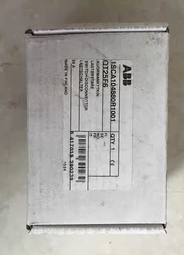

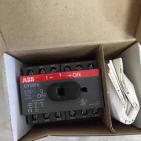
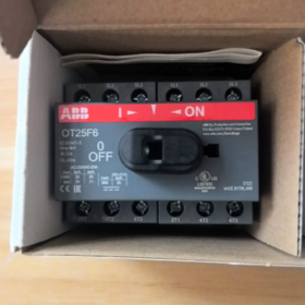
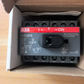
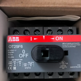
注文番号: 1SCA104880R1001, フィンランド製. ハンドルとシャフトは付属しません; 操作アクセサリは別途注文する必要があります.
型式コードの説明
OT: OTシリーズ負荷遮断器開閉器
25: 定格動作電流 25A
F: フロント操作; ベースネジ取り付けおよびDINレール取り付けに対応
6: 6-ポール (6P)
コアの電気仕様
| アイテム | パラメータ |
| 極数 | 6P |
| 定格動作電流 Ie (AC-21A) | 25 あ |
| 従来熱電流 Ith | 32 あ |
| 定格絶縁電圧Ui | 750 交流電圧 |
| インパルス耐電圧 Uimp | 8 kV |
| 端子 | 保護されたクランプ端子; 銅導体 0.75‑10mm² |
| 機械的耐久性 | 20 000 操作 |
| 保護等級 | フロントIP20 |
| 短絡耐性 (25Aヒューズ付き) | 50 kA |
| HSコード | 85365080 |
機械的寸法
幅×高さ×奥行き: 70 ×68×68mm. 入力/出力ケーブルはトップインボトムアウトまたはボトムイントップアウトで配線可能.
取り付け & 付属品
- 取り付けオプション: DIN35レールクリップオン取り付け + ベースネジ留め
- ⚠️ハンドルと操作軸はベースユニットに付属しません. ハンドルアセンブリ (例えば. OHSシリーズ) 動作させるには別途購入する必要があります; ドアに取り付けられた外部操作がサポートされています.
- 補助接点ブロック (OA1Gシリーズ) オプションのアドオンとして取り付けることができます.
- OFF位置で南京錠が可能で、メンテナンスを安全に隔離できます。.
代表的な用途
PV 結合器ボックス用の多回路 AC/DC 絶縁, エネルギー貯蔵システムとUPS
周波数変換器およびソフトスターター用の制御キャビネット内のメンテナンス断路器
6-極構成: 3-段階 + 3-DC回路絶縁, デュアル三相絶縁シナリオ
同等 & 置換参照
オリジナル ABB: OT25F6ベースユニットのみ; OT25FT6 と混同しないでください (FT=ドアマウントタイプ)
国内代替リファレンス: チント NH2-25-6P, デリックス 6P-25A ディスコネクター (置換え前に取付寸法と端子容量を確認してください)
よくある落とし穴
- OT25F6 はベースユニットのみとして提供されます. ハンドルは付属しておりません; 直接手動での作動は不可能. プロジェクトの順序付けではハンドルが省略されることがよくあります.
- Fを混ぜないでください (ベース / DINレールマウント) そしてFT (ドアマウント) バリエーション. 機械的に交換不可能です.
- AC-23A 使用カテゴリーでのモーター負荷動作には電流ディレーティングが必要です.
ABB OT25F6 の取扱説明書 (OTシリーズ) スイッチ・ディスコネクター
⚠️重要な注意事項: OT25F6 ベースユニットには四角ドライブシャフト穴のみが取り付けられています. ハンドルやシャフトは工場出荷時に取り付けられていません. OHS / OHB ハンドル アセンブリは操作前に取り付ける必要があります. 裸のシャフト穴を直接回転させないでください。.
2つのハンドルタイプ
- キャビネット内ダイレクトハンドル (OHS): スイッチ本体の前面に取り付けて筐体内で操作します。.
- 外部ドア取り付けハンドル (OHB / OHYS): 延長角軸と組み合わせて使用; キャビネットのドア表面に取り付けられたハンドル. ドアインターロック搭載: スイッチがオンのときにキャビネットのドアが開かない (通電状態). ドアはスイッチがオフの場合のみ開くことができます.
標準手動クローズ / オープンオペレーション
近い (の上, 回路に通電する): 「カチッ」と音がして機構がロックされるまで、ハンドルを時計回りに回転させます。. ハンドルマーカーをIに合わせます / 接点を完全に閉じるための ON 位置.
開ける (オフ, 絶縁回路): 「カチッ」と音がして機構がロックされるまで、ハンドルを反時計回りに回します。. ハンドルマーカーを次の位置に合わせます 0 / 安全な絶縁ギャップを確立するための OFF 位置.
✅常に完全にロックされた位置まで回転してください。. 中間位置では接触不良や過熱の原因となります。.
心臓 (ロックアウト-タグアウト) メンテナンス用
ロックはOFF位置でのみ可能です (ON 位置でのロックはサポートされていません).
- ハンドルをOFFの位置まで完全に回します.
- ハンドルの南京錠の掛け金を跳ね上げます.
- 南京錠を取り付ける (最大. 3 同時に南京錠をかける, エンドユーザーが提供する南京錠). ハンドルは回転しないように機械的にロックされており、メンテナンス中のエネルギー遮断を実現します。.
- ロックを解除する: 南京錠を外す, 掛け金をリセットする, その後、動作を再開します.
補助接点信号伝達 (オプションのOA1Gアクセサリ)
補助接点ブロック装着時:
スイッチON時, 補助接点の状態変化, PLCまたは表示灯に位置フィードバック信号を提供.
補助接点は機械式スイッチの位置に追従します, 主回路電圧の存在に依存しない.
安全上の注意事項
- OT 開閉器は、AC-21A デューティで定格負荷を切り替えることができます. モーター負荷 AC-23A アプリケーションの電流軽減. 短絡電流を遮断することはできません; ヒューズまたはサーキットブレーカーを上流に設置する必要がある.
- 詰まったハンドルを無理に引っ張らないでください. ハンドルが固着した場合, 機器の電源を切り、機械的な障害物を調査します。.
- ドアインターロックバージョンの場合: ON のときにドアを開けることができないのは通常の安全機能です. ドアを無理にこじ開けないでください. メンテナンスのためにキャビネットを開ける前に、必ずスイッチをオフにしてください.
- このデバイスは絶縁機能のみを提供します. メンテナンス作業前に必ずゼロ電圧を確認してください, スイッチがOFFでも.
- ケーブル入力 / ケーブルの引き出し方向は逆にできます (トップインボトムアウトまたはボトムイントップアウト) 動作ロジックを変更せずに.
一般的な動作上の症状
| 症状 | 根本的な原因 | 救済策 |
| ハンドルが回転できない | 南京錠が外されていない; ドアインターロック応力; 異物の詰まり | 南京錠を外す; ドアが完全に閉まっていることを確認する; 電源を切って機構を点検する |
| ハンドルがオンの位置にあると出力電力がありません | ハンドルが完全に固定されていない; 端子の緩み | しっかりと回してONディテントにします; ケーブル端子を締め直す |
| キャビネットのドアが閉まらない | 延長シャフトの長さが不適切で機械的干渉が発生する | 延長シャフト挿入深さの調整 |
一般的な障害 & ABB OT シリーズ スイッチディスコネクターのトラブルシューティング (OT25F6を含む)
安全上の警告: すべてのメンテナンス作業は、電源を切断し、LOTO ロックアウトを適用した状態で実行する必要があります。. OTシリーズベースユニットは分解修理できません。. 内部接点または機構が損傷した場合はユニット全体を交換してください. ハウジングを開けないでください.
- 硬い / 詰まった / 回しにくいハンドル
| 故障原因 | 解決 |
| 南京錠がかかっています; キャビネットのドアが完全に閉まっていない (OHB外部ハンドルインターロック) | 南京錠を外す; 操作する前にキャビネットのドアを完全に閉めてください |
| 延長角軸が長すぎるか短すぎる, エンクロージャに対する機械的結合 | シャフトの長さを調整する; 2〜3mmのクリアランスを維持する; 強引な力を加えないでください |
| 機構の隙間にゴミや金属片が侵入 | 電源を切る, 乾いた布で拭いてください; ユニットを液体溶剤で洗い流さないでください |
| 内部の機械的摩耗または詰まり | 無理にハンドルを操作しないでください; スイッチ・ディスコネクター全体を交換してください |
よくある間違い: ハンドルを取り付けずに、ベースユニットの裸の角シャフトボアを決してひねらないでください; 内部機構が破壊される.
- 無負荷出力, ハンドルがオンの位置にあるときの欠相または断続的な導通
| 故障原因 | 解決 |
| ハンドルは中間の非ロック位置で停止 | カチッという音が聞こえるまでハンドルを回転させ、ON マーカーと位置合わせします。 |
| 端子ネジの緩み; 不適切な導体の圧着 | 電源を切って端子を締め直します; 裸銅線の露出を防ぐ |
| 上流の供給がない; 上流のヒューズが切れた | 受電側電圧の確認; 上流の保護装置を検査する |
| 主接点の内部浸食 (過負荷または大電流スイッチング) | 各極間の連続性を測定. いずれかの極に断線が見られる場合は、ユニット全体を交換してください. |
- スイッチ本体の過熱 / ホット端子 / 焼けるような匂い
| 故障原因 | 解決 |
| 端子締付トルク不足; 圧着不良 | 端子を規定トルクで増し締めする; フレキシブル銅導体にはフェルールを使用する |
| 継続的な過負荷; AC‑23A モーターデューティでのディレーティングの失敗 | 動作電流を確認する; ヒューズを取り付ける / 短絡保護として上流にサーキットブレーカーを設置 |
| 小さめのケーブル断面 | 定格電流に合わせてケーブルサイズを選択してください |
| 激しい接触侵食と高い接触抵抗 | 熱検査により過熱を確認; すぐにユニット全体を交換してください |
- OFF位置でも出力側は通電状態を維持 (孤立の喪失)
| 故障原因 | 解決 |
| ハンドルがOFFディテントで完全にロックされていない | 反時計回りに完全に回して 0/OFF ロック位置にします |
| 溶接閉可動接点 (過負荷 / 短絡衝撃) | すぐに電源を切ってください; スイッチ・ディスコネクター全体を交換してください; サービスを継続しないでください |
| 寄生型 / 下流配線の誘導電圧 (スイッチ障害ではない) | 生死確認の実施; 外部回路の誘導電圧の痕跡源 |
- ドアインターロック故障 (OHB外部ドアハンドル)
| 症状 | 救済策 |
| スイッチがオンのときにキャビネットのドアが開く可能性があります (インターロック障害) | 四角軸挿入深さの確認; アクセサリのアセンブリが適切であることを確認する; ハードウェアが損傷している場合はハンドルアセンブリを交換してください |
| ドアが閉まっているとハンドルをオンの位置に閉じることができません | ドアが完全にラッチされていない; ドアの隙間と延長シャフトの深さを調整します |
- 取り付けられた OA1G 補助接点からの信号の欠落または反転
| 故障原因 | 解決 |
| 補助接点ブロックが所定の位置に完全にクリップされていない | 電源を切る, 補助接点ブロックを取り外して、ラッチがかかるまで再度取り付けます |
| 補助接点端子の誤配線 | いいえを確認してください / OA1GのNC端子定義 |
| 補助接点内部の損傷 | 補助接点ブロックのみを交換してください; メインスイッチユニットはそのまま使用可能 |
- LOTO南京錠機能が失敗する; OFF位置でロックできない
| 故障原因 | 解決 |
| 南京錠の掛け金タブが完全に開いていません | 南京錠をかける前に、ロック掛け金を完全に持ち上げてください |
| ハンドルアクセサリのロック掛け金の機械的損傷 | ハンドルアセンブリ全体を交換します |
- 異常な直流回路性能 (PV / エネルギー貯蔵用途)
症状: 開閉動作中の激しいアーク放電
原因: 標準の OT-F AC 定格開閉器の DC 遮断容量は限られています. 高圧直流回路用, 専用の OTDC DC 定格開閉器を選択してください. 標準の OT25F6-6P を繰り返し DC 負荷遮断任務に使用しないでください。; 接触腐食が発生します.
OT シリーズ開閉器の定期メンテナンス ガイドライン
- 6か月ごとに目視検査を実施: 端子の変色を確認する / 過熱, スムーズなハンドル操作を確認する. 中間の操作位置を避ける.
- プラスチック製のハウジングを液体や溶剤で掃除しないでください。; 乾いた布のみでほこりを拭き取ってください.
- スイッチハウジングは絶対に分解しないでください. 内部接点または機構が損傷した場合はユニット全体を交換してください.
- スイッチ・ディスコネクターは短絡障害を遮断できません. ヒューズまたはサーキットブレーカーを上流に設置する必要がある.
ABB OT シリーズ スイッチ ディスコネクターの設置に関する注意事項 (OT25F6)
OT-Fに適用 (レールの / ベースマウント) 範囲. すべての設置作業は、資格のある電気技術者による電圧検証を行った上で、通電されていない状態で実行されます。. ハンドルとシャフトはベースユニットに付属していないため、別途注文する必要があります; これは最も頻繁に行われるエラーです.
- 機械的設置
- 取付方法
- DIN35レール取付: DIN レールにクリップし、下部ラッチを完全に係合させて、振動による脱落を防ぎます.
- ベースプレートネジ取付: M4ネジを使用してください; 斜めに締める. 片側の固定によりハウジングに過度のストレスを与えないでください。.
- 取付方向: 垂直, 水平または天井取り付け (反転した) インストールは許可されます; パフォーマンスは変わらず.
- モデルの差別化:
OTxxF: DINレールに取り付けられたユニット / ベースプレート; キャビネット内OHSハンドルまたはドア外付けOHBハンドルと互換性があります.
OTxxFT: ドアマウントタイプ; キャビネットのドアパネルに直接取り付けられるユニット. OTxxF と機械的に互換性はありません.
- 外部ドア取り付けハンドル (OHB / OHYS) + 拡張角軸取り付け
- 延長シャフトを正確な長さにカットします. 組み立て後は2~3mmの軸方向クリアランスを維持してください. シャフト余長詰まり機構; シャフトが短すぎるとドライブが切断され、動作不能になります。.
- 組み立て後にドアインターロック機能を確認する: ON時はドアが開かないこと; ドアはOFFのときのみ開くことができます. インターロックが失敗した場合, シャフトの挿入深さを調整する; 決して無理にキャビネットのドアをこじ開けないでください.
- ハンドル取り付け後, スイッチ本体とハンドルの位置マーカーが同期していることを確認します; 位置オフセットなし.
- 補助接点ブロックの取り付け (OA1G)
- 確実なラッチのカチッという音が聞こえるまで、補助接点ブロックを横向きにユニットにクリップします。. 座りが悪いと信号損失が発生する.
- 補助接点端子締付トルク: 0.4-0.8 N・m. トルクが大きすぎると小型端子ハウジングに亀裂が発生します.
- 電気配線 (OT25F6)
- 必須のケーブル入力方向はありません: トップインボトムアウトまたはボトムイントップアウトの両方の配線が可能です.
- 導体仕様: 0.75-10 mm² 銅導体. 多芯フレキシブルケーブルにはワイヤーフェルールを使用; 短絡を引き起こす可能性がある露出した緩いストランドを避けてください。.
- 端子締め付けトルク: 2.2 N・m. トルクレンチを使用する; 手の感覚に頼らないでください. トルクが低いと熱過熱が発生する; オーバートルクによる端子ハウジングの破損.
- IP20のタッチセーフティ保護を維持するために、配線後に端子保護カバーを取り付けてください。.
- Switch-disconnector cannot break short-circuit current. Fuses or circuit-breakers must be fitted upstream.
- Derate current for motor-load circuits under AC-23A utilization category.
Ⅲ. Installation for DC Applications (PV / Energy-Storage)
- Standard OT-F AC-rated switch-disconnector has limited DC breaking performance. 高圧直流回路用, 専用の OTDC DC 定格開閉器を選択してください. Do not repeatedly break DC load-current using OT25F-6P; arcing will erode contacts.
- Strictly observe positive-/negative-polarity wiring according to datasheet for DC-circuit connections.
- 環境条件
- Ambient operating temperature: -25 ℃ ~ +60 ℃. Current derating required above +40 ℃.
- Altitude rating: ≤ 2000 m. Derate insulation and current for installation altitude > 2000 m.
- Enclosure minimum protection class IP20. Avoid heavy dust, metallic particles, corrosive gas and condensation. 沿面距離や絶縁劣化を防ぐため、結露条件下でエンクロージャ ヒーターを設置してください。.
- ユニットを屋外の天候や雨にさらさないでください。.
- 設置後の試運転チェック
- 複数の完全なオン/オフ サイクルを実行する. 鮮明なラッチ動作を確認, スムーズな動き, 中間の戻り止め位置なし.
- LOTOロックアウトテスト: 南京錠がオフの位置に取り付けられることを確認します; ハンドルが回転に対してロックされる.
- 補助接点テスト: ON時の信号の正確性を測定 / OFFスイッチング周期.
- 通電前試験: 極間および対地間の絶縁抵抗測定.
- 通電による試運転: 定期的に端子の異常な温度上昇を点検してください。.
- 禁止行為
- ❌ハンドルを取り付けずに裸の角軸ボアを回転させないでください。; 内部機構の損傷が発生します.
- ❌スイッチハウジングを分解しないでください。. 内部機構が損傷した場合はユニット全体を交換してください; 現場での修理は許可されていません.
- ❌スイッチ・ディスコネクターをサーキット・ブレーカーの代わりの短絡保護装置として使用しないでください。.
- ❌詰まったハンドルを無理に動かさないでください. 電源を切って機械的原因を調査します.
- ❌設置時にスイッチ本体内に金属片が落ちるのを防ぎます。, 内部ショートやジャミングの原因となる可能性があります.
Ⅶ. 典型的なインストールエラーの概要
| 故障現象 | 根本的な原因 |
| ハンドルが回らない | 長すぎる延長シャフトバインディング; ドアが完全に閉まっていない; 南京錠が解除されていない |
| ON位置では電力出力なし | ハンドル位置オフセット, 不完全な関与; 端子トルク不足; 挿入不足のドライブシャフトの切断 |
| ドアインターロックが機能しない | シャフト挿入深さ不適正; 付属品の組み立てが不完全 |
| 端子過熱 | 締め付けトルク不足; フェルールのないフレキシブル導体 |





NH42-63-318x560.png "CHINT PC型自動切替スイッチ (ATS)NH42-63/4SZ")



