 コンタクタ,サーキットブレーカー,センサー,エンコーダ,PLC,コンバータ

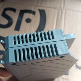
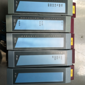
基本情報
シリーズ: B&Rシステム 2005 (廃止)
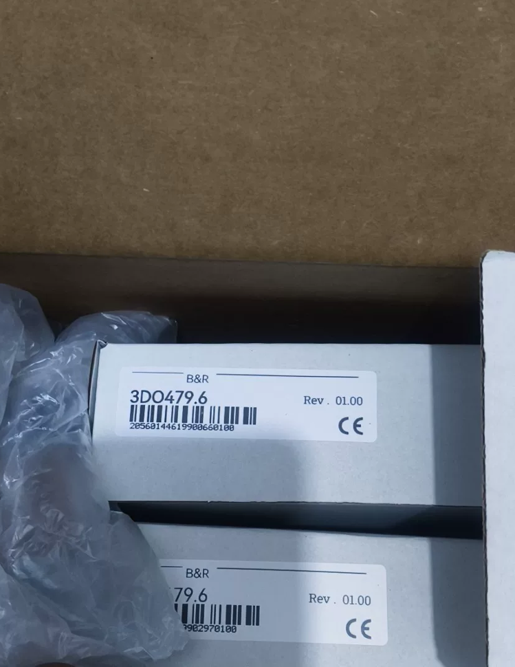
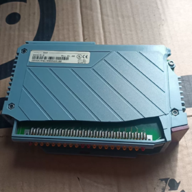
名前: DO479 Digital Transistor 出力モジュール
完全なモデル番号: 3DO479.6
コアの電気仕様
| アイテム | 仕様 |
| チャンネル数 | 16 デジタル出力 |
| 出力タイプ | NPN transistor, シンク, 24 VDC |
| チャンネルあたりの定格電流 | 0.5 あ / Ch |
| Isolation Grouping | 2 groups with galvanic isolation between groups; no isolation between channels within the same group |
| 動作電圧 | 24 VDC (external power supply for loads) |
| 消費電力 | 外部24V: 4.0 W; Backplane 5V: 1.0 W |
| ステータス表示 | Individual LED status indicator per channel |
| 短絡保護 | Onboard short-circuit protection for channels; no channel diagnostic feedback (key difference from 3DO487.6) |
Mandatory Matching Terminal Blocks (Not included with module)
3TB170.9: 20-pin screw terminal block
3TB170.91: 20-pin spring-cage terminal block
Comparison of Similar Models within the Series
| モデル | チャンネル | Current per Channel | Isolation Groups | Output Diagnostic Feedback |
| 3DO479.6 | 16する | 0.5あ | 2 isolated groups | ❌ No status feedback |
| 3DO487.6 | 16する | 2.0あ | 2 isolated groups | ✅ Supports channel diagnostics |
| 3DO480.6 | 32する | 0.5あ | 2 isolated groups | ❌ |
Replacement Solution for Phase-Out (System2005 → X20)
⚠️ Not plug-and-play compatible. Modifications required for backplane, terminal wiring and IO mapping in program.
オプション 1: Best functional match for new projects
X20DO4649
16する, 24VDC Sink, 0.5あ, grouped isolation, no diagnostics; electrically closest to 3DO479.6
オプション 2: With fault diagnostics (Recommended for equipment retrofits)
X20DO4529
16する, 0.5あ, with short-circuit diagnostics, convenient for on-site troubleshooting
Engineering Notes
- Model Distinction: 3DO479.6 ≠ 3DO487.6. The latter offers higher current capacity and channel diagnostics; avoid mixed procurement.
- 負荷制限: Freewheeling diodes are recommended for inductive loads (電磁弁, シリンダー) トランジスタの故障を防ぐため.
- Spare Part Status: Original manufacturer production discontinued. Available stock mainly includes used/refurbished units and limited new surplus; lead time and price fluctuate significantly.
- Wiring Guidance: Sink output configuration. Connect 24V+ to load, then load to DO terminal; internal module circuit connects to 0V.
典型的なアプリケーションシナリオ
包装機械, textile equipment, 小規模生産ライン, driving 24V solenoid valves, indicator lights and miniature relays.
Complete Troubleshooting Guide for B&R 3DO479.6
Important Premise: The 3DO479.6 has no built-in channel diagnostic feedback! The PLC program cannot detect short-circuit or hardware damage on channels. LEDs and multimeter measurements are required to distinguish module failures from external wiring/load faults.
- Normal Operating Status Reference
- Backplane power supply healthy: RUN green LED steady ON
- Channel LED status: PLC output ON → corresponding LED ON; PLC output OFF → LED OFF
- 出力タイプ: NPNシンク
標準配線: 24V+ → Load → DO Terminal; internal module path connects to 0V when energized.
- Step-by-Step Troubleshooting (From Simple to Complex)
ステップ 1: Inspect Power Supply and Backplane (Eliminate base/backplane faults first)
- Verify stable 5V backplane power supply for System2005 rack;
- Remove and re-seat the module, check backplane pins for oxidation or bending;
- Cross test by swapping module positions: install the tested 3DO479.6 into a known good rack slot; install a confirmed good unit into the current slot.
If fault disappears after relocation → Backplane / base fault
If fault persists after relocation → Fault resides in module hardware or program configuration
Common RUN LED faults
RUN LED completely OFF: Loss of backplane power, internal module fuse blown or hardware failure
RUN LED flashing: Bus communication error (rack, backplane, incorrect CPU address configuration)
ステップ 2: Preliminary LED Check (Quick screening)
Force corresponding channel ON via PLC software:
- ✅ Channel LED illuminates → Bus communication intact, module receives command correctly
- ❌ LED fails to light after forcing ON
First verify IO address and hardware configuration match;
If address is correct and LED still off → Internal module logic circuit failure
重要: LED only confirms command reception. LED ON does NOT guarantee valid output at terminals!
ステップ 3: Multimeter Measurement (Separate module faults from external load faults)
Measurement condition: External 24VDC load power connected
Meter setting: DC Voltage
通常の動作状態 (Channel ON)
Voltage between DO terminal and 24V 0V ≈ 0~2V (transistor conducting)
Channel OFF: Voltage between DO terminal and 0V ≈ 24VDC
Fault Phenomenon Judgement Table
| 現象 | 結論 |
| Channel forced ON, LED lit, terminal remains at 24V (transistor fails to conduct) | Internal channel hardware damage |
| Channel forced ON, LED lit, output cuts off after several seconds with flickering LED | Channel overload/short-circuit triggering internal protection |
| Channel permanently connected to 0V even when OFF (permanent conduction) | Output transistor breakdown (module damaged) |
| Multiple channels fail simultaneously while RUN LED stays on | Faulty output driver chip on module |
| Single channel failure, all other channels work normally | Single-channel transistor burnout |
⚠️ Critical test method: Disconnect all external wiring!
Remove all field cables from terminal block, conduct forced output test under no-load condition:
Abnormal performance under no-load → Module hardware failure
Normal no-load test, failure occurs only with load connected → External short circuit, leakage load or faulty solenoid coil
- Unique Pitfalls for 3DO479.6 (Frequent Misjudgements)
- No software diagnostics
Unlike the 3DO487.6, this module provides no short-circuit or wire-break feedback. PLC system alarms cannot be used to judge channel integrity.
- Grouped power supply design with two independent circuits
Terminals are divided into two groups with separate external 24V load power supply.
Loss of power for one group disables all channels within that group while the other group remains functional. This is often mistaken for module damage.
- High risk of channel burnout without freewheeling diodes for inductive loads
Solenoid valves and relay coils without parallel freewheeling diodes generate reverse electromotive force, breaking down output transistors, resulting in permanent ON or failed output channels.
- Typical Signs of Permanent Hardware Damage
- Single channel fails to output (LED ON with no terminal conduction)
- Uncontrolled permanent channel conduction (transistor breakdown)
- Complete failure of all channels within one group (faulty grouped driver circuit)
- RUN LED does not light after power-up; no indicator response (blown internal fuse or main circuit failure)
- Intermittent operation after minor short-circuit events
- Quick Troubleshooting Summary
- Swap slot position to rule out backplane faults;
- Disconnect field wiring and perform no-load testing to isolate external faults;
- Force channel status and compare LED status with multimeter voltage readings;
- Abnormal no-load performance = module fault; normal no-load performance with loaded failure = peripheral circuit fault.
- 修理 & Spare Part Recommendations
The module belongs to the discontinued System2005 platform. On-board component repair is not recommended due to poor long-term reliability after surface-mount component replacement.
Spare part solutions:
Temporary replacement: Used 3DO479.6 modules
Long-term retrofit: Migrate to X20DO4649; requires terminal wiring modification and IO address adjustment in PLC program.
Complete Procedure for Verifying 3DO479.6 Integrity
Core Premises:
✅ 3DO479.6 no channel diagnostic feedback, PLC alarms cannot assess channel status;
✅ Output type: NPNシンク;
✅ Two independent groups for external load power supply;
✅ LED only indicates command reception, LED ON ≠ valid terminal output.
準備
ツール: 24V DC電源, digital multimeter, B&R programming software, terminal screwdriver
Core principle: Test under no-load condition first, then test with load. Distinguish module hardware faults and external wiring faults.
ステップ 1: Check Rack and Communication (Confirm overall module operation)
- Mount module on System2005 backplane, power on and observe RUN LED
RUN 常時点灯: Backplane 5V power and bus communication normal
ランオフ: バックプレーンの接触不良, backplane power failure or internal module burnout
RUN flashing: Incorrect bus address, faulty backplane or module hardware defect
- Cross-slot testing (most effective method)
Install unit under test into a confirmed good rack slot; install a known good 3DO479.6 into the current slot.
Fault persists after relocation → Suspect module hardware
Fault disappears after relocation → Original rack/base/backplane fault
If RUN LED fails to light, module hardware damage is highly probable.
ステップ 2: No-Load Channel Test (致命的! Remove all external wiring)
Disconnect all field cables from terminal block. Only keep backplane connection; disconnect external load power supply.
Force channel ON/OFF via programming software and measure voltage between DO terminal and 0V using multimeter:
Acceptable Benchmark
Channel forced ON: DO ↔ 0V ≈ 0~2V (transistor conducting)
Channel forced OFF: DO ↔ 0V ≈ 24V (transistor cut off)
Test Result Judgement
- Channel forced ON, LED lit, voltage remains constant at 24V
👉 Internal channel transistor open circuit, module channel damaged
- Channel permanently shorted to 0V even when OFF
👉 Output transistor breakdown, module damaged
- All channels within one group fail while the other group works normally
👉 Faulty grouped power supply / driver circuit on module
- All channels pass no-load testing → Module hardware intact; fault lies in external wiring, load or external 24V power supply
ステップ 3: Loaded Verification (Only performed after passing no-load test)
Reconnect wiring and energize external 24V load supply, repeat forced output test.
Normal no-load behaviour, failure occurs under load:
① External short-circuit; ② Load current exceeds 0.5A rating; ③ Missing freewheeling diode for inductive loads
✅ Module itself is undamaged!
Common Misjudgement Scenarios
- All channels in one group stop output, other group works normally
👉 First check external 24V power supply for this group. Loss of external power is not equivalent to module failure.
- LED lights up but solenoid valve does not actuate
LED only confirms command reception; terminal voltage measurement is mandatory.
- Intermittent solenoid valve operation
Mostly caused by missing freewheeling diodes; reverse voltage gradually destroys output channels (detectable via no-load testing).
Checklist of Typical Module Failure Symptoms
Any of the following strongly indicates module damage:
- No RUN LED illumination after power-up, no indicator activity;
- Under no-load condition, LED turns ON on forced command but terminal cannot conduct;
- Permanent channel conduction to 0V under no-load status;
- Multiple channels malfunction under no-load test;
- Obvious overheating, odour or bulging components when powered on.
On-Site Quick Inspection Formula
Remove field wires → No-load measurement;
Swap rack slots → Eliminate backplane faults;
LED status is not equivalent to output; rely on multimeter readings;
Abnormal no-load test = faulty module; normal no-load, loaded failure = peripheral fault.
B&R System2005|Full Series Matching Models for 3DO479.6
Platform: システム 2005 (廃止); 3DO479.6 16-channel NPN transistor output module
- Mandatory Terminal Accessories (別途注文)
| モデル | タイプ | 説明 |
| 3TB170.9 | 20-pin screw terminal block | Original for 3DO479.6, screw connection |
| 3TB170.91 | 20-pin spring-cage terminal block | Tool-free push-in wiring |
- Digital Output Modules Interchangeable within the Same Rack
| モデル | チャンネル | Output Spec | Key Comparison vs 3DO479.6 |
| 3DO479.6 | 16する | 24VDC Sink, 0.5A/チャンネル, 2 isolated groups | No channel diagnostic feedback (reference model) |
| 3DO487.6 | 16する | 24VDC Sink, 2.0A/チャンネル, 2 isolated groups | ✅ Short-circuit diagnostics, より高い電流定格 |
| 3DO480.6 | 32する | 24VDC Sink, 0.5A/チャンネル, 2 isolated groups | 32-point output, no diagnostics |
| 3DO486.6 | 8する | リレー出力, 4あ, 孤立した | Relay contact type, non-transistor |
| 3DO650.6 | 8する | Source transistor output | PNPタイプ, opposite wiring polarity |
| 3DO750.6 | 8する | High-current transistor output | For heavy load applications |
- Commonly Used Matching Digital Input Modules
| モデル | チャンネル | 仕様 |
| 3DI475.6 | 16から | 24VDC, 4 isolated groups, シンク/ソース対応 |
| 3DI477.6 | 32から | 24VDC, 8 isolated groups |
| 3DI486.6-1 | 32から | 高速, 0.1ミリ秒の応答時間 |
- Mixed IO Modules (から + する)
3DM476.6: 16から + 8する
3DM486.6: 16から + 16する
- System Infrastructure (Backplane, 電源, CPU, 通信モジュール)
Power Supply Modules (Leftmost slot on rack)
3PS465.9: 50W, standard mainstream unit (推奨)
3PS477.9: High-power alternative
CPU Controllers
3CP340.60-1 / 3CP360.60-1 / 3CP380.60-1 / 3CP382.60-1
Communication Interface Modules (3IF Series, compatible on same rack)
3IF661.9, 3IF671.9, 3IF672.9, 3IF761.9, 3IF772.9, 3IF789.9 (Profinet/Profibus/CANopen/Ethernet)
Backplane Carriers (3BP Series, select based on slot count)
3BP152.4, 3BP155.4, 3BP180.4 (5-スロット / 8-スロット / 12-スロット)
- Analogue Modules (オプションの拡張)
3AI375.6, 3AI775.6, 3AM050.6, 3AM055.6, 3UM161.6 (Combined AI+DI)
Important Compatibility Reminders
- All above models can be mixed and installed on the same System2005 backplane with shared bus communication;
- Terminal blocks are NOT interchangeable!
DO479/487/480 series require 3TB170.9 / .91 (20-ピン)
32DI modules use TB718 terminals; do not mix.
- Retrofit reminder: Migration to X20 platform is not plug-and-play. Modifications needed for backplane, wiring and PLC IO mapping.
- Procurement note: 3DO479.6 ≠ 3DO487.6. Direct replacement is prohibited; availability of channel diagnostics is the core difference.
B&R System2005|Project Procurement List for 3DO479.6 (Forwardable to Suppliers)
Platform: システム 2005 (Fully Obsolete, only surplus new stock or tested used/refurbished units available)
Core Module: 3DO479.6 16-channel NPN transistor output module, no channel diagnostics
- Core IO Modules
| モデル | 説明 | 仕様 | 備考 |
| 3DO479.6 | Digital Output Module | 16する, 24VDC Sink, 0.5A/点, 2 isolated groups, no channel diagnostic feedback | 対象機種; cannot directly replace 3DO487.6 |
| 3DI475.6 | デジタル入力モジュール | 16から, 24VDC, 4 isolated groups, sink/source universal | Most common matching DI module for projects |
| 3DI477.6 | デジタル入力モジュール | 32から, 24VDC, 8 isolated groups | For projects requiring large IO counts |
| 3DM476.6 | Mixed IO Module | 16D+8C | Space-saving cabinet alternative |
| 3DM486.6 | Mixed IO Module | 16D+16C | High-capacity integrated IO module |
- Matching Terminal Blocks (Supplied Separately, NOT included with modules!)
| モデル | 説明 | Applicable Modules | 配線タイプ |
| 3TB170.9 | 20-pin terminal block | 3DO479.6 / 3DO487.6 / 3DO480.6 | ネジ接続 |
| 3TB170.91 | 20-pin spring-cage terminal block | 3DO479.6 / 3DO487.6 / 3DO480.6 | Push-in spring connection |
✅ Procurement Tip: 1 unit of 3DO479.6 requires 1 unit of 3TB170.9 or 3TB170.91
- Rack Infrastructure (For complete PLC assembly)
Power Supply Modules (Leftmost rack slot)
3PS465.9: 24VDC input, 50W, スタンダードモデル (推奨)
3PS477.9: High-power alternative
CPU Controllers (Select as required)
3CP340.60-1
3CP360.60-1
3CP380.60-1
3CP382.60-1
Communication Interface Modules (3IF Series)
3IF661.9: RS232+RS485
3IF671.9, 3IF672.9: できる / Serial interfaces
3IF789.9: プロフィバス-DP
3IF791.9: X2X Link expansion bus
Backplane Carriers (3BP Series, select slot quantity)
3BP152.4: 5-slot carrier
3BP155.4: 8-slot carrier
3BP180.4: 12-slot carrier
- Analogue Expansion Modules (オプション)
3AI375.6: Analogue input module
3AI775.6: Multi-channel analogue input module
3AM050.6 / 3AM055.6: Analogue output module
Important Procurement Terms (Forward to suppliers together)
- Series requirement: B&R System2005 series. Full model suffix must be confirmed, no abbreviations. Distinguish 3DO479.6 / 3DO487.6 to avoid incorrect delivery.
- Supply status: Original production discontinued. Priority to confirm surplus new stock or fully tested used units; modules must pass power-on and channel function testing prior to delivery.
- Terminal compatibility: Only 3TB170.9 / 3TB170.91 fit 3DO479.6; other TB series terminals cannot be mounted.
- Electrical specification: 3DO479.6 is NPN Sink output with no software channel diagnostics. Do not interchange directly with diagnostic-equipped 3DO487.6.
- Long-term retrofit suggestion: New projects are not recommended to adopt System2005. Recommended replacement model: X20DO4649 (Hardware incompatible; backplane, wiring and PLC program modifications required).
Simplified Spare Parts Inquiry Template (Direct Copy for RFQ)
Requirement List:
- 3DO479.6 × ___ pcs
- 3TB170.9 (ネジ端子) × ___ pcs
OR 3TB170.91 (スプリング端子) × ___ pcs
要件: All units to undergo power-on and channel output function testing before shipment.





NH42-63-318x560.png "CHINT PC型自動切替スイッチ (ATS)NH42-63/4SZ")



