 コンタクタ,サーキットブレーカー,センサー,エンコーダ,PLC,コンバータ



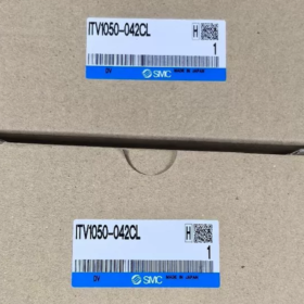
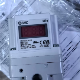
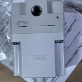
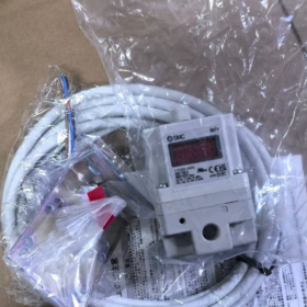
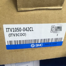
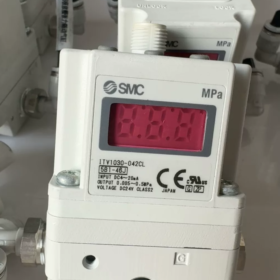
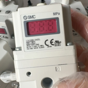
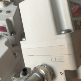
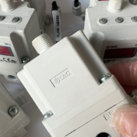
ITV1050-042CL
- ITV: SMC Electro-Pneumatic Regulator Series
- 10: 1000 シリーズ (compact single-body unit)
- 50: Output pressure range 0.005~0.9 MPa
- 0: Power supply DC24V; Control input 4~20mA (Sink type)
- 4: Monitor feedback output 4~20mA (Sink type)
- 2: Port thread Rc1/4
- C: Equipped with L-shaped mounting bracket
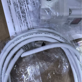
- L: Cable connector right-angle type with 3m cable
Comparison Reference:
ITV1050-042N = Without cable; ITV1050-042S = Straight cable; suffix L stands for right-angle outlet.
- 主要な技術仕様
| アイテム | パラメータ |
| Output Pressure Range | 0.005~0.9 MPa |
| マックス. Supply Pressure | 1.0 MPa; Minimum supply pressure = Target output pressure + 0.1 MPa |
| 電源 | DC24V ±10%, Current consumption ≤0.12A |
| Control Input | 4~20mA DC (シンク) |
| Pressure Feedback Output | 4~20mA DC (シンク) |
| Linearity | ±1% F.S. |
| ヒステリシス | ≤0.5% F.S. |
| Repeatability | ±0.5% F.S. |
| 感度 | 0.2% F.S. |
| 侵入保護 | Body IP65, Connector IP67 |
| 動作温度 | 0~50℃ (air medium, 結露なし) |
| Port Specification | Rc1/4 (SUP supply / OUT output / EXH exhaust) |
- Cable Pin Definition (Right-angle 3m Cable)
Wire color assignment:
茶色: DC24V+
青: DC24V 0V (パワーマイナス)
白: 4~20mA control signal +
黒: 4~20mA pressure feedback output +
⚠️ Critical Note: Signal negative terminal must share common ground with power negative. Floating wiring is prohibited.
- Port Definition
SUP: Supply air inlet
外: 負荷出力 (connect to cylinder, fixture, nozzle)
EXH: Exhaust port; Do not block. Fit silencer in dusty environments.
- 代表的な用途
Pressure regulation for laser cutting, フィルムの張力制御, precision pressing, spray pressure control, semiconductor vacuum chucking, stepped pressure simulation for test equipment, textile pneumatic tension control.
- 選択 & Replacement Guidance
- Direct interchange within the same series: ITV1050-042CL cannot be replaced with ITV1050-312CL (312 is 0–10V voltage input).
- 代替アップグレード: ITV2050 new generation series (larger dimension, higher flow capacity).
- Reminder for domestic alternatives: 信号の種類 (シンク/ソース) is prone to miswiring; always verify input & output signal specifications.
- Common Troubleshooting Points
- Unstable output pressure: Verify supply pressure differential ≥0.1 MPa, air line leakage, excessive load volume.
- Drifting feedback signal: Ensure low power supply ripple, shield grounding, and separate signal cables from power cables.
- Panel display “LOC”: Press and hold the left button to unlock parameter menu.
Flow Characteristics of SMC ITV1050-042CL (ITV1050 Series)
ITV1050-042CL belongs to the compact ITV1000 series with Rc1/4 ports and 0.005~0.9 MPa pressure range. Flow parameters are identical for all ITV1050 variants (suffixes only affect signal, bracket and cable; internal flow passage remains unchanged).
- Rated Flow Rate (Standard Test Condition)
Test condition: Supply pressure Ps=1.0 MPa, set output pressure 0.6 MPa, standard air (ANR)
- Maximum charging flow (SUP→OUT): ≈200 L/min (ANR)
- Maximum exhausting flow (OUT→EXH): ≈120 L/min (ANR)
✅ Key Feature: Exhaust flow is lower than charging flow. Pressure release of large-volume loads will be significantly slower than pressure build-up.
- Flow Capacity Parameters (SMC standard pneumatic notation, ISO 6358)
Sonic conductance C (SUP→OUT charging): 0.13 dm³/(エス・バー)
Sonic conductance C (OUT→EXH exhausting): 0.08 dm³/(エス・バー)
Critical pressure ratio b ≈ 0.5
These values can be directly adopted for simulation calculation of charging/exhaust time for air tanks and cylinders.
- Flow Characteristic Rules (Core Properties)
- Non-linear regulated flow
The ITV is not a continuous throttling valve. It adopts two built-in high-speed solenoid valves (charge valve + exhaust valve) controlled by PWM:
Steady pressure holding: Charge and exhaust valves nearly closed, only minor leakage compensation;
Pressure rising: Charge valve adjusts intake flow by varying PWM duty cycle;
Pressure falling: Exhaust valve adjusts exhaust flow by varying PWM duty cycle.
👉 Output flow is not constant; it dynamically changes with pressure differential and target pressure deviation.
- Influence of pressure differential
Larger differential between supply and output pressure enables higher instantaneous maximum flow;
Minimum supply pressure requirement: Supply pressure ≥ Target output pressure + 0.1 MPa
If the pressure differential is less than 0.1 MPa, maximum flow drops sharply and pressure response slows down.
- Coupling between load volume and dynamic response
Small-volume loads (suction fixture, nozzle): Excellent pressure tracking performance;
Large-volume air tanks / large-bore cylinders: Longer charging & exhausting time, prone to overshoot.
Engineering experience: Install an external quick exhaust valve to accelerate pressure release if volume>1 L.
- 応答時間 (Dynamic indicator correlated with flow)
Test condition: 供給圧力 1.0 MPa, load volume 50 mL
Rise time 0→0.5 MPa: ≤0.8 s
Fall time 0.5→0 MPa: ≤1.0 s
Charging and exhausting time increases approximately linearly with load volume.
- Flow-Related Usage Restrictions (選択の落とし穴の回避)
- Not suitable for continuous high-flow operation
The ITV1000 is a pressure-prioritized proportional regulator. Its design objective is pressure stabilization. Long-term operation near the maximum 200 L/min flow will cause internal pilot valve overheating and pressure fluctuation.
Solution for continuous high-flow applications: Use the ITV to pilot a large-capacity external pressure regulator.
- Line pressure loss greatly reduces effective flow
Recommended tubing inner diameter ≥6 mm; thin and long tubing makes actual flow at the load far lower than the rated 200 L/分.
- Do not block the exhaust port
Blocked EXH port drastically reduces exhaust capacity and slows pressure release. Fit compact silencers in dusty environments.
- Flow Capacity Comparison within Series
| シリーズ | マックス. Charging Flow (ANR) | 位置決め |
| ITV1050 (このモデル) | 200 L/分 | コンパクト, medium-low flow |
| ITV2050 | 800 L/分 | 中流量 |
| ITV3050 | 4000 L/分 | 高流量 |
Applicable Scenarios for Flow Characteristic Curves of SMC ITV1050-042CL
中核的な前提:
ITV1050 is a closed-loop pressure-controlled electro-pneumatic regulator driven by PWM high-speed switching valves. The flow characteristic curves provided in the datasheet (max flow vs output pressure, charging/exhaust capacity, C-value curves) describe the ultimate air supply/exhaust capacity of the valve under different pressure differentials.
It is NOT equivalent to the flow curve of a proportional throttle valve. The curves can only be used to evaluate pressure build-up/release speed and maximum allowable air consumption, and cannot be applied for precise flow control.
- Scenarios Where Flow Curves Can Be Directly Used for Calculation & 検証
- Closed fixed-volume loads (Most Typical Application)
負荷: Air tanks, suction cavities, airtight test chambers, vacuum suction platforms, closed pressure regulating tooling
目的:
Calculate pressure rise/release time with flow curves and C values, verify maximum allowable cavity volume, predict pressure switching response speed, and judge insufficient response or pressure overshoot.
Reference limit: Recommended volume ≤1 L; evaluate external quick exhaust valves for larger volumes.
- Short-stroke, low-air-consumption pneumatic actuators
負荷: Short-stroke diaphragm cylinders, precision pressing heads, クランプシリンダー, micro lifting cylinders
アプリケーション: Precision pressing, lamination tooling, small fixture pressure control
Verification objective:
Instant air consumption during cylinder movement must be lower than the maximum charging flow (200 L/min ANR) to prevent pressure drop and loss of stability during operation.
- Stable low-flow continuous air output (nozzles, air curtains, air blowing)
負荷: Small-bore blowing nozzles, narrow air curtains, laser auxiliary blowing, small cooling air nozzles
前提条件: Stable continuous air consumption, long-term flow <150 L/min
Function of curve: Confirm continuous air consumption does not exceed the ultimate flow capacity of the valve; assess flow loss caused by tubing pressure drop.
注意: Avoid long-term operation near the 200 L/min flow limit, which leads to continuous heating of internal solenoid valves and pressure oscillation.
- Dynamic stepped pressure cycle testing
Process requires frequent switching between multiple set pressure levels (high/low pressure cyclic impact test)
Flow curves are used to estimate pressure rise/fall duration, compare with allowable process switching time, and evaluate whether to add air accumulators or external quick exhaust valves to optimize pressure release.
- Scenarios Where Flow Curves Only Serve Rough Reference, Accurate Simulation Not Feasible
- Long-stroke, large-bore cylinders with continuous reciprocating motion
Cylinders continuously consume air and form dynamically variable flow loads. Pressure drop occurs when air consumption approaches the valve flow limit. The flow curve can only judge the upper flow limit and cannot precisely calculate cylinder operating speed.
Engineering suggestion: Adopt the scheme of “ITV pilot + large-capacity pressure regulator” for high air consumption conditions.
- Loads with frequent drastic flow fluctuation and no buffer volume
Sudden airflow variation easily triggers pressure oscillation. Static flow curves cannot characterize dynamic oscillation behavior and can only be used for preliminary selection reference.
- Scenarios Where Flow Curves Are Completely Inapplicable – Misuse Strictly Forbidden
- Processes requiring precise gas flow control (constant flow delivery, micro airflow regulation)
The ITV targets pressure control. Flow varies automatically with inlet-outlet pressure differential; flow remains inconsistent under identical set pressure. Flow curves cannot be used as control basis. Electro-pneumatic proportional flow valves shall be selected instead.
- Independent and precise exhaust flow control required
The ITV only implements pressure closed-loop control. Exhaust flow is adjusted indirectly via pressure feedback. Stable independent exhaust flow regulation cannot be achieved.
- Design of continuous high-flow working conditions
Long-term continuous air consumption >150 L/min; direct driving via ITV is not recommended.
- エンジニアリングの概要
✅ Suitable to apply flow curves for response, volume and air consumption verification:
Closed cavity pressure regulation | Small short-stroke cylinders | Stable low-flow air blowing | Cyclic pressure testing
⚠️ Rough reference only: Large-bore long-stroke cylinders, loads with frequent flow fluctuation
❌ Not applicable: Constant flow control, precise independent exhaust flow regulation





NH42-63-318x560.png "CHINT PC型自動切替スイッチ (ATS)NH42-63/4SZ")



