 コンタクタ,サーキットブレーカー,センサー,エンコーダ,PLC,コンバータ

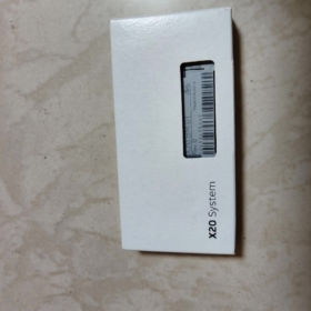
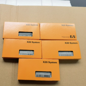
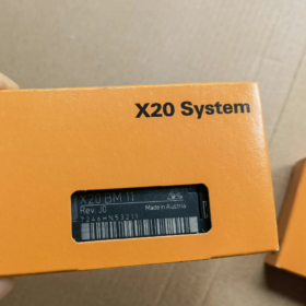
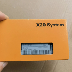
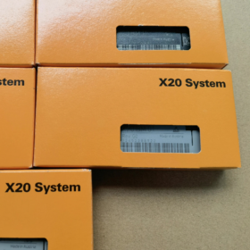
モデルの位置決め
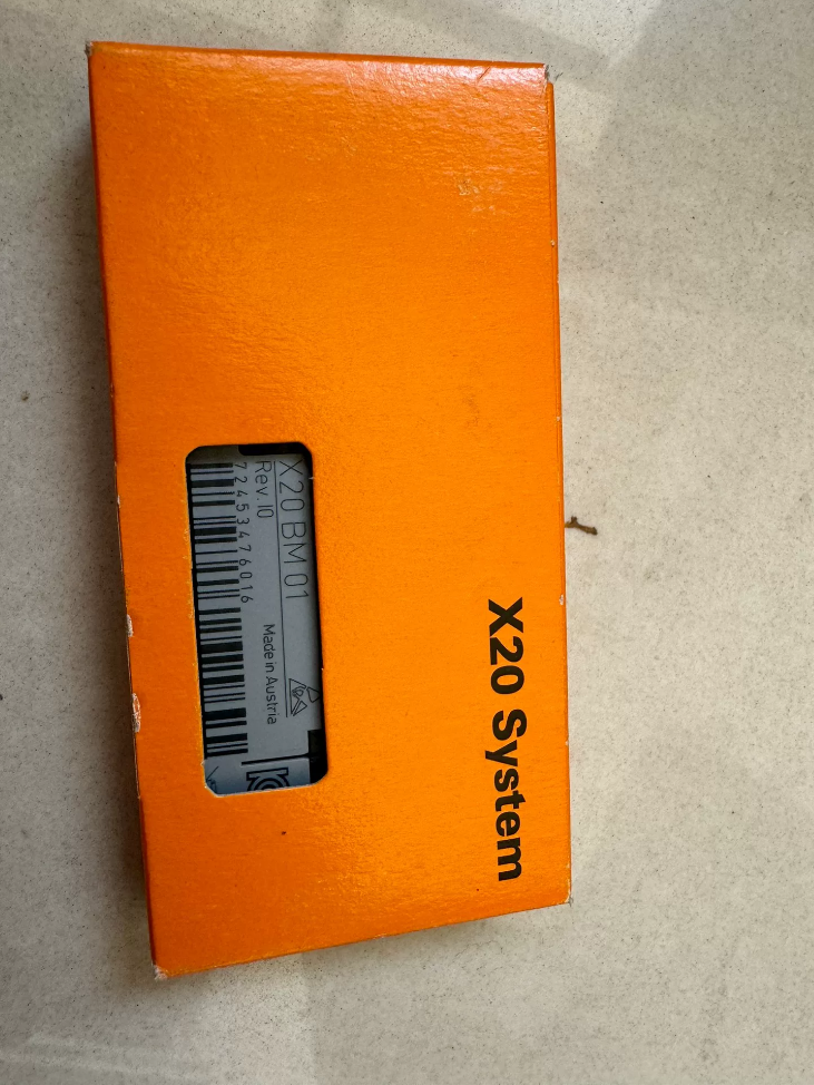
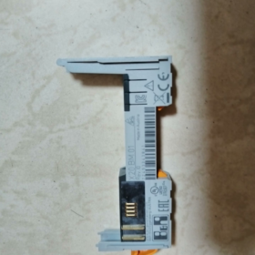
X20BM01 = Power Bus Base Module for the B&R X20 System
Chinese Name: Power Bus Base Module
Core Feature: The internal I/O supply is disconnected to the left and only conducts to the right. It is used to create independent potential groups and works in conjunction with X20 power supply modules (X20PSxxxx).
コア機能の説明
- Carries the X2X Link backplane communication bus (communication signals between left and right modules are connected).
- Unidirectional transmission of the I/O supply rail: Modules on the right receive power; modules on the left cannot draw I/O power via this module.
- Serves as the mandatory mating base for X20 power supply modules (X20PS3300 / X20PS9400, 等).
- Enables potential isolation of I/O segments. Multiple independent 24 VDC I/O supply zones can be configured on one continuous bus rail.
重要な区別 (Common Selection Pitfall)
X20BM01: I/O supply disconnected left, conducted right (unidirectional power supply, preferred for segment isolation)
X20BM11: I/O supply bidirectionally connected (I/O power linked across the entire DIN rail)
- 完全な技術仕様
| アイテム | 仕様 |
| モデル | X20BM01; コンフォーマルコーティングバージョン: X20cBM01 |
| 消費電力 (bus circuit) | 0.13 W |
| Rated I/O supply voltage | 24 VDC |
| Permissible load of I/O supply contacts | 10 あ |
| モジュール幅 | 12.5 mm |
| 保護クラス | IP20 (キャビネット取り付け専用) |
| 取り付け | 35 mm DINレール |
| 動作温度 (水平取り付け) | -25 ℃~ +60 ℃ |
| 動作温度 (垂直取り付け) | -25 ℃~ +50 ℃ |
| ストレージ / 輸送温度 | -25 ℃~ +70 ℃ |
| 相対湿度 | 5%~95%, 結露しないこと |
| 認証 | CE, UKCA, cULus, ATEXゾーン 2, DNV/ABS marine certification, HazLoc Class 1 ディビジョン. 2 |
- ハードウェア構造 & Wiring Logic
- Conductivity rules for three signal/power paths:
✅ X2X communication bus: Continuously connected between left and right modules
✅ Bus supply (controller supply): Connected between left and right modules
❌ Field I/O supply rail: Disconnected to the left; power only passes to the right
- Application Specifications:
X20PS power supply modules must be clipped onto the BM01. の 24 VDC I/O power generated by the power module can only supply all I/O modules installed to the right of the BM01.
If two mutually isolated I/O power zones are required on one rail, install one X20BM01 between the two zones to separate the I/O supply.
Suitable scenarios: Separate I/O power for different machine sections, preventing loss of all I/O caused by a short-circuit at a single point.
Unsuitable scenario: All I/O modules on the rail share one 24 VDC電源 (select X20BM11 in this case).
- 選定ガイドライン & よくある落とし穴
- X20BM11 cannot replace X20BM01 unconditionally
X20BM11 provides bidirectional power continuity and eliminates potential isolation. Short-circuit faults will propagate across segments. Special topologies apply to power redundancy schemes.
- One X20PS power supply module shall only be paired with one BM01 base; multiple power supplies cannot share a single X20BM01.
- Automation Studio hardware catalog: Minimum supported version V4.2, minimum module firmware 2.2.0.0.
- For dusty or humid environments, order X20cBM01 (with conformal coating).
- Common Matching Components
Power base module: X20BM01
Bidirectional power base module: X20BM11
Rail termination base module: X20BM05
Power supply modules: X20PS3300, X20PS9400
Application Scenarios of B&R X20BM01
Recap of core electrical characteristic:
X2X communication bus and controller bus supply are bidirectionally connected; field 24 VDC I/O supply is disconnected to the left and only conducted to the right.
関数: Divide I/O supply segments on the DIN rail to implement independent segmented power supply and fault isolation. X20PS power modules must be mounted on X20BM01.
Reference benchmark: X20BM11 provides bidirectional I/O power continuity across the rail and cannot implement segment isolation.
- Standard Typical Application Scenarios
1.1 Independent I/O Power Supply for Multiple Machine Sections (最も一般的な)
Machines with multiple independent motion units require separated 24 VDC I/O power supplies, avoiding complete I/O failure caused by short-circuit of a single sensor.
トポロジー:
コントローラ / remote head → General input modules → X20BM01 + X20PS → All I/O for Machine Section 1
The BM01 isolates power; modules on the left do not draw power from this 24 VDC電源.
Applicable equipment:
射出成形機, ブロー成形機
包装機械 (segmentation for feeding, 封印, 並べ替え & discharging stations)
Machine tool automation, stamping manipulators
New energy lithium equipment: Independent I/O zoning for calendering, slitting and winding stations
利点: A short-circuit at one station only stops the local segment; the controller and I/O of other sections remain operational.
1.2 Power Separation Between Digital I/O and Analog Modules
Industry best practice: Analog signals (プレッシャー, 温度, encoder signals) should avoid sharing the same 24 VDC supply with high-power digital outputs (電磁弁, インジケーターランプ), to prevent interference from inductive loads affecting analog sampling accuracy.
トポロジー:
Analog module bank → X20BM01 + power supply → Solenoid valve / relay output module bank
Suppresses transient disturbance from high-power loads on AI/AO modules and encoders, improving analog signal stability.
1.3 Potential Separation Between Safety Circuits and Standard I/O
Safety-related signals (安全ゲート, 非常停止, safety light curtain inputs) use an independent power supply, separated from power for standard actuators.
X20BM01 divides the rail into segments: one zone for safety I/O, another for general actuators.
重要な注意事項: Power segmentation cannot replace safety relays or safety PLCs. It serves only as an auxiliary measure for electrical noise reduction and fault isolation.
1.4 Voltage Drop Optimization via Multi-point Power Supply on Long DIN Rails
When more than approx. 12~16 I/O modules are installed on one rail, a single 24 VDC cable will suffer excessive voltage drop.
解決: Install additional X20BM01 + X20PS assemblies along the rail for segmented power feeding.
Applicable equipment: Large conveying lines, automated warehouse sorting cabinets, large coating production line control cabinets.
1.5 Segmented Power Supply for Remote X20 Nodes (X2X Link Remote Stations)
X20BC remote bus controllers (EtherCAT / POWERLINK remote heads) extend a continuous DIN rail:
The remote head supplies power to the front group of modules
Additional BM01 + external power supply installed mid-rail to provide independent power for rear I/O modules
Suitable for remote control cabinets on large production lines and remote I/O stations for multi-station mobile equipment.
- Industry-Specific Deployment Scenarios
- 食品包装 & 製薬機器
Industry specifications require separated power supply for actuators in clean zones and internal control signals inside cabinets. Reduces disturbance from solenoid valve switching on weighing modules and flowmeters.
- New Energy Lithium & 太陽光発電装置
Higher risk of sensor cable breakage and short circuits in dusty environments. Segmented power supply prevents a single short-circuit from disabling all I/O on an entire remote station and reduces production downtime.
- 港湾機械 & Marine Equipment (DNV certified)
Control cabinets have compact layout with densely packed modules. Segmented power supply mitigates voltage fluctuation and suits vibration-prone operating conditions.
- ゴム & プラスチック押出成形, Cast Film Production Lines
Large quantities of heating elements and solenoid valves (誘導負荷). Strict power separation from temperature acquisition modules to prevent temperature signal fluctuation.
- Scenarios Where X20BM01 Is NOT Suitable
- All I/O modules on the DIN rail share a single external 24 VDC supply → select X20BM11
- Termination at the far end of the DIN rail → use X20BM05 (X20BM01 must not be used as rail terminator)
- Pure communication extension without requirement for additional independent I/O power supply
- Requirement for bidirectional disconnection of I/O supply (BM01 only cuts power to the left; bidirectional isolation cannot be achieved)
- Engineering Design Guidelines & 落とし穴の回避
- X20PS power supply modules can only be mounted on BM01, not on BM11 or BM05.
- Current calculation: Total current of all modules to the right of each BM01 shall not exceed the rated 10 A of the base module.
- Do not mount multiple X20PS power modules on one X20BM01.
- If independent power supplies are required for both left and right sides, deploy two X20BM01 modules back-to-back in the topology.
- 簡単な選択の概要
Independent 24 VDC I/O supply required for segment fault isolation → X20BM01
Continuous power across the whole rail with no segmentation needed → X20BM11
Rail end termination module → X20BM05





NH42-63-318x560.png "CHINT PC型自動切替スイッチ (ATS)NH42-63/4SZ")



