CHINT NP2 series push buttons are master control electrical appliances applicable to industrial control circuits.
Scope of Application
Suitable for industrial control circuits with AC 50Hz/60Hz, rated operating voltage up to 415V, and DC operating voltage up to 250V. They can be used for controlling electromagnetic starters, 接触器, relays and other electrical circuits. Push buttons with indicator lights are also suitable for light signal indication scenarios. Compliant with the standard GB/T 14048.5.
Model Designation and Interpretation
The model is usually designated as NP2-□□□□□□□□□□ □□□, どこ “NP” stands for CHINT push buttons, “2” is the design serial number, and the subsequent codes represent dimension code, structure classification, type code, auxiliary specification code, 等, in sequence. 例えば, the dimension code D30 shall be marked as Φ30, while the dimension code D22 can be omitted; “B” indicates a metal-headed button, そして “E” indicates a plastic-headed button.
Normal Operating and Installation Conditions
Ambient air temperature: -5℃ ~ +40℃, with the average temperature not exceeding +35℃ within 24 hours; 高度: not exceeding 2000m; Pollution degree: Level 3; Installation category: Category Ⅱ. The buttons should be installed in places free from significant shaking, shock, vibration, rain and snow erosion, and in media without explosion risks, corrosive gases that can damage metals and insulation, or excessive dust.
Main Parameters and Technical Performance
Rated insulation voltage: 415V; Conventional heating current: 10あ. Mechanical service life: 1,000,000 cycles for flat-headed and mushroom-headed buttons, そして 100,000 cycles for other types. Electrical service life (AC): 500,000 cycles for flat-headed and mushroom-headed buttons, そして 100,000 cycles for others; Electrical service life (DC): 200,000 cycles for flat-headed and mushroom-headed buttons, そして 100,000 cycles for others. Protection class options: IP40, IP65.
Structure Types
Available in multiple types including flat-headed, mushroom-headed, rotary-knob, and key-operated buttons. 例えば, NP2-EA□□ is a plastic-headed flat button, NP2-EC□□ is a plastic-headed mushroom button, NP2-D is a rotary-knob button, and NP2-G is a key-operated button.
Installation Dimensions of CHINT NP2 Push Buttons
CHINT NP2 series push buttons have two standard installation dimensions: Φ22mm and Φ30mm, corresponding to different models and application scenarios.
- Φ22mm Specification (Most Common)
Panel Hole Diameter: Φ22.3<sub>0</sub><sup>+0.4</sup>mm (22.3mm, upper deviation +0.4mm)
Applicable Panel Thickness:
Metal-headed type (Series B): 1mm ~ 6mm
Plastic-headed type (Series E): 1mm ~ 4mm
- Φ30mm Specification
Panel Hole Diameter: Φ30.5<sub>0</sub><sup>+0.5</sup>mm (30.5mm, upper deviation +0.5mm)
Applicable Panel Thickness: 1mm ~ 3mm
- Installation Methods
Metal-headed type: Insert the operating head into the mounting hole from the front of the panel, screw the base into place from the rear of the panel, and evenly tighten the fastening screws at both ends (torque ≤ 0.8N·m).
Plastic-headed type: Remove the base first, then tighten the nut during installation (torque: 1.2~1.8N·m).
- Minimum Spacing Requirements Between Buttons
Minimum center distance between adjacent button mounting holes (mm):
| Button Type | 22 インストール | 30 インストール |
| Flat-headed, Rotary-knob | 30 | 50 |
| Mushroom-headed | 40 | 50 |
| Illuminated, Signal Light | 30 | 50 |
| Double-headed Button | 30 | – |
The standard installation dimension of CHINT NP2 push buttons is Φ22mm (hole diameter: 22.3+0.4mm), suitable for most industrial control scenarios; the special specification is Φ30mm (hole diameter: 30.5+0.5mm). When purchasing and installing, please confirm that the button model matches the panel thickness.
Working Principle of CHINT NP2 Push Buttons
CHINT NP2 series push buttons are self-resetting master control electrical appliances (some rotary-knob/key-operated models are self-locking type). Their core function is to control the on-off of internal contacts through manual mechanical operation, thereby transmitting control signals to drive the action of executive components such as contactors and relays, without directly carrying high-power loads.
- Core Structural Components
- Operating Components: Operating heads such as flat head, mushroom head, rotary knob, and key, used to receive manual commands.
- Reset Mechanism: Built-in reset spring, which is the core component for self-resetting function.
- Contact Module: Consists of Normally Open (いいえ) contacts and Normally Closed (ノースカロライナ州) 連絡先. The contacts are made of silver alloy material to improve conductivity and electrical service life.
- Base: Fixes the contact module, provides wiring terminals, and ensures insulation performance.
- Additional Components for Illuminated Models: LED indicator light and current-limiting resistor (used to protect the indicator light from burnout due to overcurrent).
- Working Principle of Self-resetting Push Buttons (Mainstream Models, 例えば, Flat-headed, Mushroom-headed)
- Initial State
The reset spring is in a naturally extended state, NC contacts remain closed, and NO contacts remain open, with the circuit operating in the initial state.
- Pressed State
Manually pressing the operating head pushes the internal push rod to compress the reset spring, triggering the linkage action of the contacts:
NC contacts open first: Cut off the original NC circuit;
NO contacts close afterward: Turn on the NO circuit to send an action signal to subsequent control components.
- Released & Reset State
When the operating head is released, the elastic force of the reset spring pushes the push rod and the operating head to reset, and the contacts return to the initial state (NC contacts closed, NO contacts open), terminating the control signal.
- Working Principle of Self-locking Push Buttons (Rotary-knob/Key-operated Models)
- First Operation: Rotate the knob or insert/remove the key; the mechanical structure drives the contact switching (NC contacts open, NO contacts close), and the self-locking mechanism locks the current contact state without the need for continuous force application.
- Second Operation: Rotate the knob in the reverse direction or insert/remove the key again; the self-locking mechanism unlocks, and the reset spring drives the contacts and operating components to return to the initial state.
- Indication Principle of Illuminated Push Buttons
The indicator light circuit of illuminated push buttons is independent of the control contact circuit:
- The indicator light is connected to a power supply of specified voltage level (例えば, AC 220V, DC 24V) through a current-limiting resistor;
- When the indicator light circuit is powered on, the LED lights up to visually display the working state of the button (or the operating state of the corresponding equipment);
- The on-off operation of the contacts does not affect the indicator light circuit, and the indicator light is only controlled by its own power supply circuit.
Core Feature Summary
The contact action of NP2 push buttons has the characteristic of break-before-make, which can avoid short-circuit risks during control circuit switching; the self-resetting design ensures that the button returns to the initial state when not in operation, improving the stability of the control logic.
コンタクタ,サーキットブレーカー,ソーラーインバーター,電気メーター,太陽電池
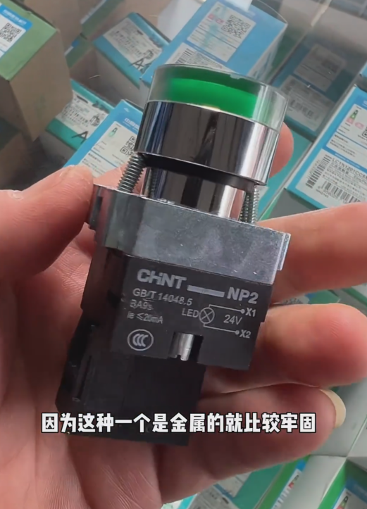


NH42-63-318x560.png)


