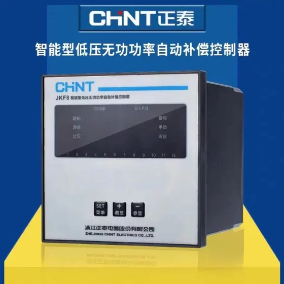
コンタクタ,サーキットブレーカー,センサー,エンコーダ,PLC,コンバータ





The DTV series is デルタ’s dedicated PID valve position controller for electric valves. Unlike conventional temperature controllers for heating/cooling loads, it is specially designed to drive modulating electric actuators with forward/reverse rotation. Panel dimension: 48×96mm (1/8 から).
モデルコードの定義
DTV: Delta Valve Controller series
4896: Panel size W48 × H96 mm
C: リレー出力 (C=Relay; R variant shares identical panel size with different contact rating/wiring)
Other models in this series include DTV9696C / DTV9696R (96×96 large panel)
主な特長
- Valve-specialized PID: Equipped with two relay outputs for valve opening / valve closing to directly drive forward/reverse rotation of electric actuators. Real-time valve opening percentage display on panel. A/M auto/manual one-touch switching; valve opening can be fixed manually in manual mode.
- Multi-input support
熱電対: K, J, T, E, N, R, S, B, U, L, TXK
Platinum RTD: Pt100, JPt100
アナログ: 4~~20mA, 0~~20mA, 0~~5V, 0~~10V
- アラーム: 2 groups of alarm outputs with 17 alarm modes (high/low limit, deviation alarm, valve fault, 等)
- コミュニケーション: Built-in RS485, Modbus RTU/ASCII. Baud rate 2400~38400bps. Connectable to PLC and SCADA for PV/SV/valve opening and alarm status acquisition.
- 電源: 100~240VAC 50/60Hz
- 画面: デュアルLED; PV in red, SV in green; ℃/℉ switchable
- Sampling speed: 0.4s for thermocouple/RTD; 0.15s for analog input
代表的な用途
Industrial kilns, heat exchangers, 空調設備, textile dyeing, hot water systems, closed-loop temperature control for electric regulating valves, constant temperature water supply/heating and furnace temperature regulation.
Difference from standard DTC/DTA temperature controllers
Standard temperature controllers: SSR/current output for heating loads.
DTV: Dual relay outputs to control forward/reverse motor of electric actuators, with valve-position PID dedicated to modulating valve opening.
Wiring Summary
OUT1: Valve open relay
OUT2: Valve close relay
ALM1/ALM2: Alarm relays
RS485: D+, D-, Modbus通信
Sensor input: 熱電対 / Pt100 / アナログ信号
注記: DTV outputs are dry relay contacts only. They cannot power the actuator directly. The electric actuator requires external AC220V power supply.
よくあるトラブルシューティング
- Valve no movement: Check ON/OFF operation of OUT1/OUT2 relays; actuator power supply and internal limit switches; improper PID P/I/D parameters.
- Temperature oscillation: Perform PID auto-tuning; reduce proportional band P and increase integral time.
- 通信障害: Verify RS485 A/B wiring, 駅の住所, baud rate and parity.
- Abnormal PV reading: Sensor open circuit, mismatched input type, reversed wiring polarity.
代替選択
同じシリーズ: DTV4896R (same panel size, contact rating difference, check datasheet)
代替: If analog output (4~20mA) for electric valve is required, DTV cannot be used directly. Select DTA/DTB with analog output.
Delta DTV4896C Modbus RTU Register Map (Hex native address from manual)
プロトコル: Modbus RTU / ASCII, スレーブ; 機能コード: 03H Read Holding Registers, 06H Single Register Write, 01H Read Coils, 05H Force Single Coil
Unit definition: PV/SV = 0.1℃ / 0.1 scale; 例えば. 250 = 25.0℃; Valve opening unit = 0.1%
⚠️ PLC/HMI commonly uses 40001 offset: Physical address 1000H = HMI address 41001
Word Registers (03H / 06H)
| 住所(Hex) | 名前 | R/W | 説明 |
| 1000H | PV Process Value | R | Real-time temperature; Fault codes: 8002H Data acquisition failure /8003H Sensor break /8004H Wrong input type /8006H ADC fault /8007H Memory fault |
| 1001H | SV Set Value | R/W | Temperature setpoint, 0.1 scale |
| 1002H | Range Upper Limit | R | Max input range |
| 1003H | Range Lower Limit | R | Min input range |
| 1004H | センサーの種類 | R/W | 0=K,1=J,2=T,3=E,4=N,5=R,6=S,7=B,8=L,9=U, 10=TXK,11=JPt100,12=Pt100,13=0~5V, 14=0~10V,15=0~20mA,16=4~20mA |
| 1005H | 制御モード | R/W | 0=PID;1=ON/OFF;2=Manual;3=Program PID;4=Ramp control |
| 1006H | Heat/Cool | R/W | 0 加熱, 1 冷却 |
| 1009H | PB Proportional Band | R/W | 0.1~999.9 |
| 100ああ | Ti Integral Time | R/W | 0~9999 |
| 100BH | Td Derivative Time | R/W | 0~9999 |
| 100CH | Integral Initial Value | R/W | 0~1000 (0.1% ユニット) |
| 100DH | Proportional Compensation | R/W | Active when Ti=0, 0~1000 (0.1%) |
| 1012H | Output Valve Opening | R/W | ユニット 0.1%; Writable only in manual mode, read-only in auto mode |
| 1018H | Valve Full Close to Full Open Time | R/W | Valve stroke time, 0.1~999.9s; critical parameter for systems without valve position feedback |
| 1019H | Valve Dead Band | R/W | ユニット 0.1%, suppress frequent valve chattering |
| 101ああ | Valve Feedback Upper Limit | R/W | For AI valve feedback: 0~1024 |
| 101BH | Valve Feedback Lower Limit | R/W | For AI valve feedback: 0~1024 |
| 101CH | PID Group Selection | R/W | 0~4; 4=Auto PID match |
| 101EH | Valve Output Upper Limit | R/W | 0.1% ユニット, maximum opening limit |
| 101FH | Valve Output Lower Limit | R/W | 0.1% ユニット, minimum opening limit |
| 1020H | ALM1 Alarm Mode | R/W | 17 alarm modes |
| 1021H | ALM2 Alarm Mode | R/W | 17 alarm modes |
| 1024H | ALM1 Upper Threshold | R/W | アラーム 1 threshold |
| 1025H | ALM1 Lower Threshold | R/W | アラーム 1 threshold |
| 1026H | ALM2 Upper Threshold | R/W | アラーム 2 threshold |
| 1027H | ALM2 Lower Threshold | R/W | アラーム 2 threshold |
| 102ああ | Panel Status Word | R | Bit0:℉ Bit1:℃ Bit2:ALM2 Bit4:OUT1 Open Valve Bit5:OUT2 Close Valve Bit6:AT Auto-tuning Bit7:ALM1 |
| 102FH | ファームウェアのバージョン | R | V1.00=0100H |
Bit Coils (01H Read / 05H Write Coil)
| 住所(Hex) | 名前 | R/W | 説明 |
| 0810H | Communication Write Enable | R/W | 0=Write disabled (工場出荷時のデフォルト), 1=Allow host PC parameter write |
| 0811H | Temperature Unit | R/W | 0=℉, 1=℃ |
| 0812H | Decimal Point | R/W | 0/1; Not valid for B/R/S thermocouple |
| 0813H | PID Auto-tuning AT | R/W | 0 停止, 1 Start AT |
| 0814H | Control Run/Stop | R/W | 0 停止, 1 走る |
| 0815H | Program Control End | R/W | 0 走る, 1 End |
| 0816H | Program Pause | R/W | 0 走る, 1 Pause |
| 0817H | Valve Position Feedback Enable | R/W | 0 No feedback, 1 AI valve feedback enabled |
| 0818H | Valve Feedback Auto-calibration | R/W | 0 停止, 1 Start stroke auto-calibration (for valves with feedback) |
Communication Basic Parameters (Set inside controller)
- Station address: 1~247
- ボーレート: 2400 / 4800 / 9600 /19200 /38400
- パリティ: Fixed 8,N,1 (7E1/8O2 not supported)
- プロトコル: Modbus RTU (推奨) / ASCII
Operation Examples (DVP PLC / HMI)
Read PV: 機能コード 03, start address `1000H`, read 1 Word
Modify SV: 機能コード 06, address `1001H`, write target value (例えば. 250 = 25.0℃)
Write valve opening in manual mode: First set `1005H` =2 (Manual mode), then write `1012H`; 例えば. 500 = 50.0% オープニング
Start PID auto-tuning: 05H write `0813H`=ON
重要な注意事項
- Before host writing parameters, 0810H must be set to 1 (communication write enable) otherwise write commands will fail. Set back to 0 after commissioning to prevent accidental modification.
- DTV is a time-proportional valve position controller, NOT a 4~20mA analog output valve controller. Without valve feedback, valve opening is calculated based on【valve full-close to full-open time】.
- For HMI with 40001 offset: Physical address 1000H = decimal 4096 → HMI address 44097 (40001+4096)
Delta DTV4896C Fault Code List (PV register read via Modbus)
注記: The DTV panel does not display hex fault codes directly. Fault codes are abnormal values read from PV register `1000H` by host system. Panel typically shows —- or EEE with ALM LED lit.
| 故障コード(Hex) | 説明 | トラブルシューティング & 救済策 |
| 8002H | Measurement not available / Input read timeout | 1. Check loose or broken sensor wiring |
| 2. Inspect terminal oxidation or poor contact | ||
| 3. Confirm sensor type parameter matches field sensor | ||
| 4. Power cycle controller to eliminate transient interference | ||
| 8003H | Sensor break (最も一般的な) | ✅Thermocouple: 極性を確認してください, 開回路; |
| ✅Pt100: One wire of 3-wire circuit broken; | ||
| ✅4~20mA analog: Loop open, no current; | ||
| Test continuity, replace sensor or repair wiring | ||
| 8004H | Wrong input type configuration | 1. Verify【Sensor Type】parameter (1004H) matches actual sensor |
| 例: K-type sensor cannot be set to Pt100; 4~20mA cannot be set as thermocouple | ||
| 2. アナログ入力: Internal jumper must be switched to current mode; wrong jumper will trigger 8004H | ||
| 8006H | ADC analog-to-digital hardware fault | 1. Power off for 5 minutes then restart to clear transient error |
| 2. Disconnect sensor, if fault persists with empty input terminals → ADC hardware damage, replace DTV unit | ||
| 8007H | Memory fault (EEPROM error) | 1. Try factory reset and reload parameters |
| 2. 電源を入れ直します; if fault remains: storage chip damaged, replace controller |
Local Panel Fault Indication (No Modbus required, visual check)
- PV display —-: Sensor open circuit, corresponds to 8003H
- PV display EEE: Input out of range, sensor short circuit or wrong input type (8004H)
- ALM LED ON but PV reading normal: Not input hardware fault. ALM1/ALM2 process alarm triggered (temperature limit, deviation or valve fault). Enter alarm menu to check alarm mode and threshold.
Valve Control Functional Faults (Not the above hardware fault codes, DTV specific)
DTV valve controller, valve no movement / frequent chattering, PV reading normal but abnormal valve action, not classified as 80xx hardware faults:
- Valve no movement
Check ON/OFF of OUT1/OUT2 relay contacts with multimeter
Verify actuator AC220V supply and internal limit switches
パラメータ:【Valve full close to full open time】1018H incorrectly set to zero will disable valve action
- Valve chattering / frequent pulsing
Increase valve dead band (1019H, ユニット 0.1%)
PID proportional band PB too small (overly aggressive P gain) causing oscillation; run AT auto-tuning
- Mismatch between displayed valve opening and actual valve position (with AI feedback)
Enable valve feedback coil (0817H=1), start valve feedback auto-calibration (0818H=1), redefine stroke upper/lower limit 101AH/101BH
General Troubleshooting Workflow (Recommended sequence)
- Power cycle to eliminate transient interference
- Verify sensor wiring and sensor integrity
- Confirm input type setting and hardware jumper (analog input must set jumper correctly)
- Read PV register via host to confirm fault code
- Software fault: Factory reset and reconfigure parameters; hardware fault (8006/8007): Replace controller directly
Important Distinction for Alarms
80xx codes = Measurement input / hardware faults (PV cannot be read)
ALM1/ALM2 alarms = Process alarms (temperature limit, 偏差, valve fault, PV acquisition normal). Do not confuse the two.
- Model Coding Rule for full DTV series
DTV + パネル寸法 + 出力タイプ
- Panel dimension (2 オプション)
4896: 48×96mm (1/8 から, your current model)
9696: 96×96mm (1/4 から)
- Suffix code (Hardware output)
C: リレー出力 (OUT1 open, OUT2 close, dual relay, 最も一般的な, DTV4896C)
R: Basic relay (single channel valve relay)
L: Linear current output (4~20mA for analog electric actuators)
V: Voltage pulse output (solid state pulse drive)
Unified power: AC100~240V; all models equipped with RS485 Modbus RTU/ASCII, dual alarm and valve PID control.
- Complete DTV Model List (Mainstream available models)
1)48×96mm (DTV4896 series, slim vertical)
- DTV4896C: Dual relay output (開ける + Close valve), dedicated for electric valves (main model)
- DTV4896R: Single relay output
- DTV4896L: 4~20mA linear current output
- DTV4896V: Voltage pulse solid-state output
2)96×96mm (DTV9696 series, square large display)
- DTV9696C: Dual relay open/close valve (same logic as DTV4896C, only larger panel)
- DTV9696R: Single relay
- DTV9696L: 4~20mA linear current output
- DTV9696V: Pulse voltage output
Universal input across all series: K/J/T/E/N/R/S/B/L/U/TXK thermocouple, Pt100/JPt100 RTD, 0~~5V/0~~10V/4~20mA analog input.
- Model Suffix Comparison
| サフィックス | 出力タイプ | 応用 | Matches your DTV4896C |
| C | Dual relay (OUT1 Open, OUT2 Close) | Electric actuators with forward/reverse rotation | ✅ Your model |
| R | Single relay | Single direction valve, simple on-off control | Alternative spare |
| L | 4~20mA analog signal | Modulating analog electric valves | Analog valve control |
| V | Voltage pulse | SSR solid state drive, contactless frequent operation | High frequency on-off control |
- 廃止 / Legacy Notes
DTV series only has 4896 そして 9696 two panel sizes, no 4848 または 7272 バリエーション;
No derivatives such as DTV4896D, DTV4896E;
Communication registers, fault codes and parameter menus: C/R/L/V share identical firmware logic, only hardware output differs.


NH42-63-318x560.png "CHINT PC型自動切替スイッチ (ATS)NH42-63/4SZ")