 コンタクタ,サーキットブレーカー,ソーラーインバーター,電気メーター,太陽電池

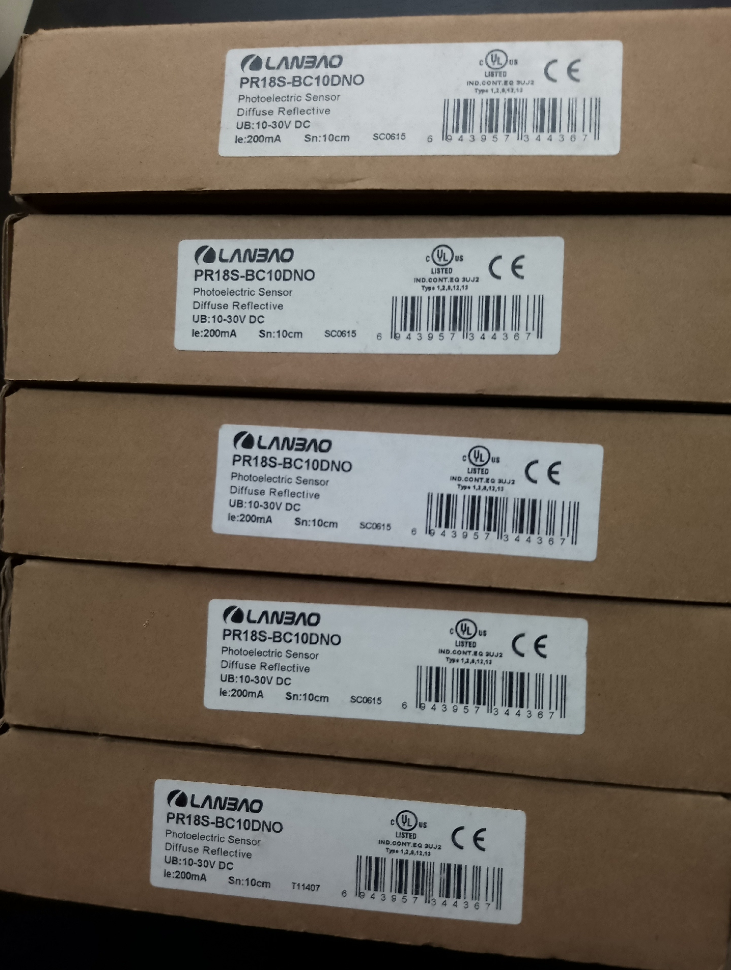


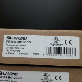
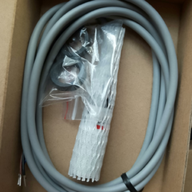
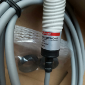
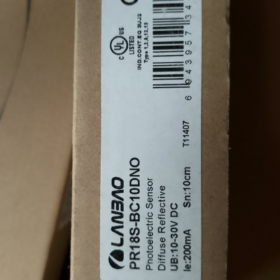
PR18S-BC10DNO is an M18 cylindrical plastic housing diffuse-reflective photoelectric sensor from LANBAO (Shanghai Lanbao Sensing) PR18S Series. It adopts a dedicated control IC for stable performance and integrates multiple circuit protections. Rated IP67 for dust and water resistance, it is a general-purpose object detection component widely used in industrial automation. It comes standard with a 2-meter PVC cable (サフィックス: -E2).
- Model Code Decoding
The full standard model is PR18S-BC10DNO-E2. The definition of each code is as follows:
PR18S: 製品シリーズ, featuring M18×1 thread, PBT plastic housing and diffuse-reflective detection principle
BC10: Detection specification
BC: 拡散反射 (direct reflection) detection mode
10: Rated sensing distance of 10cm (修理済み, non-adjustable)
D: 電源タイプ, DC 10~30VDC
N: 出力タイプ, NPN
○: 出力論理, 通常開 (いいえ; output turns on when an object is detected)
-E2 (Default suffix): ケーブル差込口, standard 2m PVC cable; suffix -C stands for M12 4-pin connector type
- 主な技術仕様
| カテゴリ | 仕様 |
| Detection Mode | Diffuse reflection (direct reflection) |
| 光源 | 880nm Infrared LED |
| 定格検出距離 | 10cm (based on 90% reflectivity white card, non-adjustable) |
| 供給電圧 | 10 ~ 30 VDC |
| 出力タイプ | 3-wire NPN Normally Open (いいえ) |
| 最大負荷電流 | ≤300mA |
| 消費電流 | ≤25mA |
| 応答時間 | <8.2ms |
| 繰り返し精度 | ≤5% Sr |
| Hysteresis Range | 3% ~ 20% Sr |
| 保護機能 | 逆極性保護, 短絡保護, 過負荷保護, サージ保護 |
| ステータスインジケーター | 黄色のLED (lights up when object is detected) |
| ハウジング材質 | PBT Engineering Plastic |
| 全体の寸法 | M18×1 thread × 53.5mm (body length) |
| 保護クラス | IP67 (Compliant with IEC Standard) |
| 動作温度 | -15℃~+55℃ |
| Ambient Humidity | 35% ~95%RH (結露なし) |
| 認証 | CE, UL |
- Full Model List of DC Diffuse-Reflective Sensors in the Same Series
| 検出距離 | NPN いいえ | NPN NC | PNP いいえ | PNP NC | NPN NO+NC | PNP NO+NC |
| 10cm (調整不可) | PR18S-BC10DNO | PR18S-BC10DNC | PR18S-BC10DPO | PR18S-BC10DPC | PR18S-BC10DNR | PR18S-BC10DPR |
| 40cm (調整可能) | PR18S-BC40DNO | PR18S-BC40DNC | PR18S-BC40DPO | PR18S-BC40DPC | PR18S-BC40DNR | PR18S-BC40DPR |
注記: All models are equipped with -E2 (2メートルケーブル) デフォルトでは; replace the suffix with -C for connector version.
- 配線の定義 (3-wire Cable Version)
Brown wire: パワーポジティブ (+10~30VDC)
Blue wire: パワーマイナス (0V / GND)
Black wire: 信号出力 (NPN いいえ; output conducts when object is detected, connect to the negative side of load)
- 代表的な用途
Workpiece presence detection and counting on automated production lines
Material detection for packaging and printing industries
Object recognition and sorting trigger on warehouse conveyor lines
Limit positioning and home position detection for equipment stations
Missing part and falling part detection for small components
- Troubleshooting Matrix for Common Faults
| 故障現象 | 根本的な原因 | 段階的な解決策 |
| Indicator off and no output after power-on | 1. 逆電源極性 | 1. Check brown and blue wires and rewire correctly |
| 2. Supply voltage out of 10~30VDC range | 2. Measure supply voltage with multimeter to ensure it is within rated range | |
| 3. Internal cable breakage | 3. Replace cable or conduct cross test with spare sensor | |
| No signal output even when object is detected | 1. Object beyond effective sensing distance | 1. Reduce the distance between sensor and object with proper margin |
| 2. Low reflectivity of measured object (ピュアブラック / light-absorbing material) | 2. Use high-reflective surface or select 40cm long-distance model | |
| 3. Wrong wiring of output circuit | 3. Verify complete connection of black output wire and load circuit | |
| 誤ったトリガー & continuous output with no object | 1. Highly reflective objects in background | 1. Adjust mounting angle to avoid reflective background |
| 2. Strong ambient light directly irradiating the receiver lens | 2. Install light shield to block strong direct light | |
| 3. Severe electromagnetic interference | 3. Route sensor cables away from power cables and ensure proper grounding | |
| Fluctuating and unstable output signal | 1. Object stays at the detection boundary | 1. Fine-tune mounting distance to stay away from critical zone |
| 2. Dust or dirt covering the lens | 2. Clean the lens with a soft dry cloth |
- 代替モデル
Upgraded model of the same brand: PR18-BC10DNO (Nickel-copper alloy metal housing with higher mechanical strength, 同一の電気的パラメータ)
Cross-brand equivalent alternatives: OMRON E3Z-D61, Schneider XUB5BNANL2
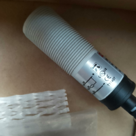
PR18S-BC10DNO is a standard M18 plastic housing diffuse-reflective photoelectric sensor manufactured by LANBAO. See physical specifications below:
- Detailed Mounting Dimensions
This sensor adopts threaded cylindrical mounting. Dimensions and mounting regulations are specified as follows:
| アイテム | 仕様 |
| Main Thread | M18 × 1mm (Metric fine thread) |
| Effective Thread Length | 30mm |
| Sensor Body Length (Excluding cable/connector) | 約. 53.5mm (cable version) |
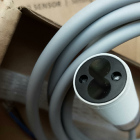
| Sensing Face Diameter | Φ18mm |
| 標準付属品 | 2 pcs M18 lock nuts, 1 pc anti-loose washer |
| Recommended Mounting Hole | Φ18.5mm through hole |
| Minimum Spacing for Side-by-Side Installation | ≥40mm (to prevent optical crosstalk) |
Mounting Instructions
- Fix the sensor on cabinet panels, brackets and other mounting positions via two lock nuts; the extension length is adjustable.
- Align the sensing face towards the moving direction of measured objects. The tilt angle is recommended ≤15°, otherwise the effective sensing distance will be reduced.
- This is a non-flush mount sensor. Do not embed the sensing face into metal mounting surface; keep the sensing face fully exposed.
- 配線の定義 & Connection Instructions
9.1 Standard Cable Version (Suffix -E2, 2m PVC Cable, 3-ワイヤー)
| ワイヤーの色 | 関数 | 説明 |
| 茶色 | パワーポジティブ (V+) | Connect to 10~30VDC positive terminal |
| 青 | パワーネガティブ (GND) | Connect to power 0V / negative terminal |
| 黒 | 信号出力 (外) | NPN Normally Open (いいえ) 出力 |
9.2 Wiring Principle of NPN NO Output
This model is NPN sinking output:
When no object is detected: Output terminal is floating, internal transistor cuts off with no signal output.
When object is detected: Internal transistor turns on, black output wire connects to blue power negative terminal and outputs low level (0V).
一般的な配線 (Connect to PLC Sinking Input)
Brown wire → 24V+ of switching power supply
Blue wire → 0V of switching power supply & PLC common terminal (COM)
Black wire → PLC digital input terminal
Wiring for Relay / Indicator Load
One end of load connects to 24V+, the other end connects to sensor black output wire.
Sensor blue wire connects to 24V-.
Single-channel load current shall not exceed 300mA. 誘導負荷の場合, connect a freewheeling diode in reverse parallel.
9.3 M12 Connector Version (Suffix -C, 4-pin Male Connector)
ピン割り当て (View from sensing face, numbered clockwise):
- ピン 1: 茶色 (力 +)
- ピン 3: 青 (力 -)
- ピン 4: 黒 (信号出力)
- ピン 2: スペア (未使用)
- 取り付け & 配線上の注意
- Polarity Protection: Do not reverse power polarity. The built-in reverse polarity protection prevents burnout, but the sensor will not work normally under reversed connection.
- Load Limit: Maximum output load current is 300mA. Do not drive high-power loads directly; use intermediate relays for transition.
- 環境要件: Avoid direct sunlight or strong LED light on the sensing window, and keep away from mirror or polished metal reflective surfaces in the background.
- EMC Requirements: Separate sensor cables from power cables (インバータ, servo cables) with a distance of ≥20cm. Do not lay them in the same conduit.


")


NH42-63-318x560.png "CHINT PC型自動切替スイッチ (ATS)NH42-63/4SZ")


