 コンタクタ,サーキットブレーカー,ソーラーインバーター,電気メーター,太陽電池


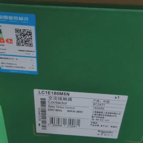
シュナイダーLC1E180M5Nは、 ACコンタクタ TeSys Eシリーズに属する, 主にモーターなどの電気負荷を制御するために設計されています.
基本情報
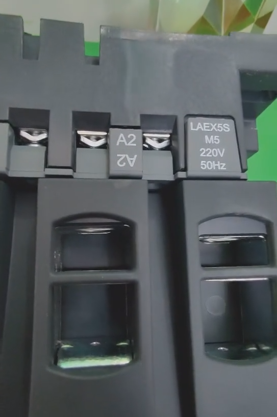
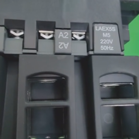
モデルの解釈: LC1 はコンタクタを指定します; EはTeSys Eシリーズを表します; 180 は定格電流を示します; M は、制御コイル電圧が 220V AC であることを意味します; 5 はコイル周波数50Hzを示します。; N は、製品が中国の規格に準拠していることを示します.
ブランド: シュナイダー
極数: 3P
主な連絡先: 3いいえ (3 つの通常開)
技術的パラメータ
定格動作電流: 18あ (AC-3 職務カテゴリー)
定格動作電圧: ≤690V AC (50/60Hz)
制御コイル電圧: 220Vと
コイル周波数: 50Hz
電気的寿命: AC-3 デューティ カテゴリでの長い電気寿命
機械的寿命: まで 10 100万操作
取付方法: DINレール取付、ベースプレート取付に対応
保護クラス: IP20, 直接指が触れないようにする
製品の特徴
長寿命: 最長の機械的寿命を誇ります。 10 100万回の動作と高い電気的寿命, 交換頻度を減らす.
強い適応力: で治療した “TH” 保護, 湿気の多い高温環境での動作を可能にする.
広い電圧耐性: コイル制御電圧は以下の範囲で変動する可能性があります。 85%-110% 製品の通常の動作に影響を与えることなくUC.
高い汎用性: 50Hz~60Hzの周波数に対応したユニバーサルコイルを搭載.
モジュラー設計: 補助接点ブロック, オンディレー/オフディレー接点ブロック, メカニカルインターロックやその他のモジュールをメインユニットに取り付け可能. また、リバーシブルコンタクタやスターデルタスタータに簡単に組み立てることもできます。.
応用分野
力率 0.95 以上の AC 負荷に最適. 正常に始動するかご型モーターの開閉に使用できます。, 工場設備などの電気負荷の制御も可能, 電気ヒーター, 工作機械や各種パワーユニット.
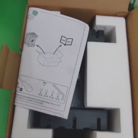
Schneider LC1E180M5N コンタクタの設置ガイド
- インストール前の準備
- 製品仕様を確認する
モデルを確認する: LC1E180M5N (TeSys Eシリーズ, 定格電流180A, コイル電圧 AC220V, 50Hz)
外観に損傷がないかを検査し、アークシュートが無傷であることを確認します。
環境が乾燥していることを確認してください, 風通しの良い, 腐食性ガスのないこと, 周囲温度範囲 -5℃~+40℃
- 道具や材料を準備する
絶縁工具 (電圧テスター, 絶縁手袋)
ドライバー (適合する端子ネジ)
トルクレンチ (推奨トルク範囲: 4-6N・m)
ケーブル (主回路: 10-50mm²; 制御回路: 1-2.5mm²)
ケーブル端子
取付レール (35mm DIN規格) または取り付けプレート
- 安全上の注意事項
危険! 感電の危険性, 爆発またはアークフラッシュ
すべての電源を切断する必要があります, LOTOに従ってロックされタグ付けされています (ロックアウト/タグアウト) インストール前の手順, 配線または試運転
– 運転前に電圧検出装置で電圧がかかっていないことを確認してください。; 計器のディスプレイだけに頼らないでください
– 設置作業は資格のある電気担当者のみが行ってください。
– 適切な PPE を着用してください (個人用保護具) 絶縁手袋と安全メガネを含む
– コンタクタの動作中は、アークシュートを開いたり、充電部分に触れたりしないでください。
Ⅲ. インストール手順
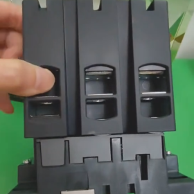
- コンタクタの固定
DINレール取付:
- コンタクタの背面にあるレール クリップを 35mm DIN レールに合わせます。
- までしっかりと押し込みます。 “クリック” 音が聞こえる, コンタクタが所定の位置にロックされていることを示します
- 削除するには, ドライバーでクリップをそっとこじってコンタクタを外します
ベースプレートの取り付け:
- を使用してコンタクタを固定します。 4 M6 ネジをユニット底部の取り付け穴に通します
- 取り付け面が平らであり、コンタクタが垂直に取り付けられていることを確認してください。 (傾斜角 <5°) 熱の放散を促進するために
- 主回路配線 (三相システム)
| 端子マーキング | 接続内容 | 説明 |
| L1/L2/L3 | 三相電源入力 | サーキットブレーカーまたはヒューズの出力端子に接続します |
| T1/T2/T3 | 負荷出力 (例えば. モーター) | モーターまたはその他の電気負荷に接続します |
操作手順:
- ケーブルの絶縁層を約 10 ~ 15 mm の長さに剥ぎます。
- 適切なケーブル端子を取り付け、しっかりと圧着します。
- ケーブルの端子を対応する端子穴に挿入し、ネジを規定のトルクで締め付けます。 (4-6N・m)
- 相間の絶縁を強化するには、相バリアを使用することをお勧めします。, 特に大電流アプリケーション向け
- 制御回路の配線
| 端子マーキング | 接続内容 | 説明 |
| A1 | 制御電源活線 (L) | 制御回路のスタート信号に接続 |
| A2 | 制御電源中性線 (N) | 制御回路のコモン端子に接続します |
| 補助接点 (13-14/21-22) | 信号フィードバックまたは連動 | オプション, 状態表示やインターロック制御に使用 |
代表的な制御回路の接続 (セルフロック制御):
- 制御電源→停止ボタン (通常は閉まっている) →スタートボタン (通常は開いています) →コンタクタ端子A1
- 端子A2→制御電源中性線
- コンタクタの補助常開接点をスタートボタンと並列に接続します (セルフロックを実現する)
- 付属品の取り付け (オプション)
補助接点ブロック (例えば. その他のシリーズ):
モジュールをコンタクタの側面にクリップして、 “クリック” 音が聞こえる, 適切な取り付けを示す
過負荷リレー (LR Eシリーズを推奨します):
コンタクタの直下に取り付け、クリップで固定します; 接続ワイヤは内部で事前に配線されています
- 試運転とテスト
- 配線検査
すべての接続がしっかりと接続されていることを確認します, 緩みやショートがないこと
端子ネジのトルクが規定を満たしているか確認してください。
位相順序が正しいことを確認してください (モーター回転方向に対応するL1-L2-L3)
- 無負荷試験 (負荷を接続しない場合)
制御電源を投入し、コンタクタの開閉動作をテストします。
コイルの過熱や異音の発生を観察する
補助接点が正しく動作するか確認してください (必要に応じてマルチメーターで測定します)
- 負荷テスト
主回路電源が切断されていることを確認し、最初にインチングテストを実行してください。
徐々に負荷を増加させ、コンタクタの温度上昇を監視します (60Kを超えないこと) そして動作音
過負荷保護機能をテストする (LR Eリレーが取り付けられている場合)
- メンテナンスに関する推奨事項
定期点検 (月に一度):
端子の接続が緩んでいないか確認してください (特に振動環境では)
接点の磨耗状態を点検する (接点摩耗インジケーターが利用可能な場合)
アークシュートが損傷していないか確認してください
異常な動作温度を監視
清掃とメンテナンス:
ほこりを掃除する前に電源を切ってください; 内部回路の洗浄に溶剤を使用しないでください。
換気経路が妨げられていないことを確認してください
- トラブルシューティング
| 問題 | 考えられる原因 | ソリューション |
| コンタクタが閉じない | コイルの電圧が無い/電圧が不足している | 制御電源と回路の接続を確認してください |
| コイルの損傷 | コンタクタを交換する | |
| 過度の動作騒音 | 汚染/酸化した鉄心接触面 | 鉄心接触面の清掃 |
| 電源電圧が不安定 | 電源の品質をチェックする | |
| 接点の過熱 | 接触不良 | 端子の増し締め (規定トルクに注意してください) |
| 過大な負荷電流 | 負荷が定格を超えていないか確認してください |
Ⅶ. まとめ
LC1E180M5N コンタクタを正しく取り付ける鍵は、次のとおりです。: 安全な電源オフ, 適切な固定, 安全な配線と包括的なテスト. このガイドに従うことで、機器の信頼性の高い動作が確保されるだけでなく、機器の耐用年数も延長されます。. インストール後, 将来のメンテナンスや検査のために、製品ラベルと取り付け記録を保管してください。.
注記: このガイドは、Schneider LC1E180M5N コンタクタおよび同じシリーズの他のモデルに適用されます。 (LC1E120~LC1E630).


")
NH42-63-318x560.png "CHINT PC型自動切替スイッチ (ATS)NH42-63/4SZ")


