 コンタクタ,サーキットブレーカー,ソーラーインバーター,電気メーター,太陽電池

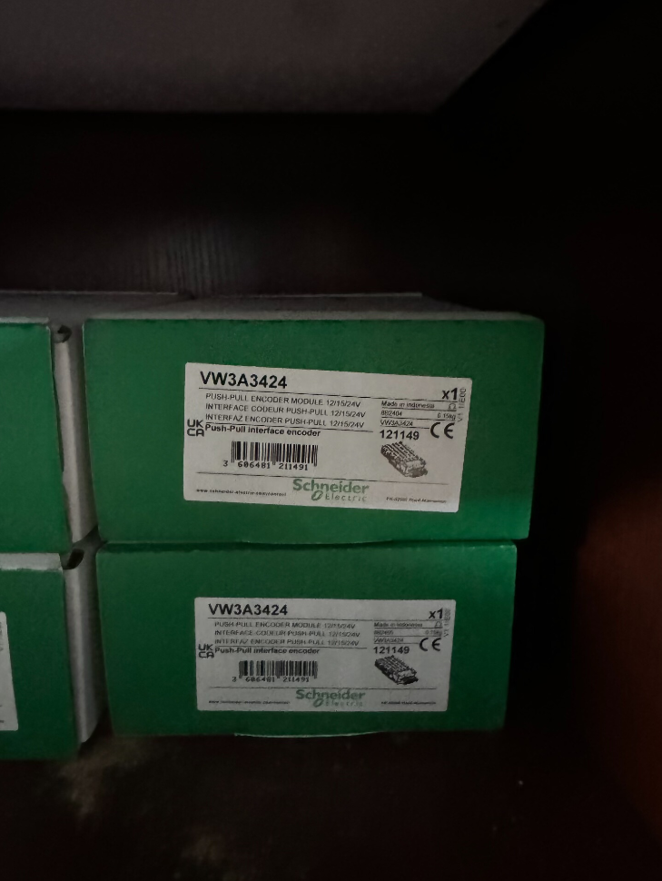

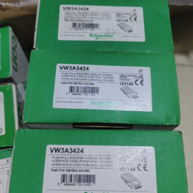
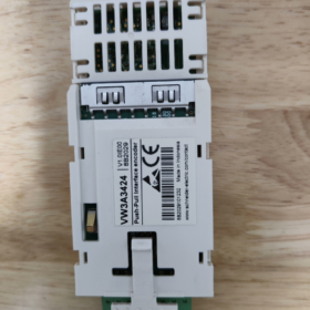
VW3A3424 は HTL です (高閾値ロジック) が開発したインクリメンタルエンコーダインターフェースオプションカード シュナイダーエレクトリック Altivar シリーズ可変速ドライブ専用, 閉ループ駆動制御の拡張アクセサリとして機能. このモジュールは、速度/位置フィードバック信号を外部エンコーダからドライブに供給して、磁束ベクトル制御を実装します。 (FVC) センサーフィードバックと同期モーターベクトル制御付き (FSY). 低速トルク出力が大幅に向上します, 速度調整精度, 動的応答性能とトルク制御精度, 安定した速度制御と高い位置決め精度を要求する産業用駆動アプリケーションに適しています。.
- モデルコーディングの内訳
| コードセグメント | 説明 |
| VW3A | Schneider Altivar シリーズ ドライブの一般的なアクセサリのプレフィックス, ドライブ オプション コンポーネントを表す |
| 34 | エンコーダインターフェイスモジュールの製品ファミリーコード, エンコーダフィードバックオプションの範囲を特定する |
| 24 | 特定のモデルの識別子, インクリメンタル エンコーダ用の広範囲の 12 ~ 24 V 電源をサポートする HTL レベル バリアントを示します。 |
Ⅲ. 主要な技術仕様
| パラメータ項目 | 仕様 |
| 製品タイプ | HTL インクリメンタル エンコーダ インターフェイス モジュール |
| 対応ドライブシリーズ | アルティバーマシン ATV340, アルティバープロセス ATV900 (ATV930/ATV950を含む), モジュラー Altivar Process ドライブ |
| エンコーダ電源電圧 | 12 ワシントンDCで / 15 ワシントンDCで / 24 ワシントンDCで (適応出力, ハードウェアの DIP スイッチ構成は必要ありません) |
| 最大供給電流 | 0.2 あ@ 12 V; 0.175 あ@ 15 V; 0.1 あ@ 24 V |
| サポートされる信号タイプ | プッシュプルディファレンシャル (あ / /あ, B / /B), プッシュプルシングルエンド (あ, B), オープンコレクタ差動 (あ / /あ, B / /B), オープンコレクタ PNP/NPN シングルエンド (あ, B) |
| 最大動作周波数 | 12 kHz |
| 最大伝送距離 | 500 メートル (ワイヤゲージと信号タイプの一致により異なります) |
| 接続方法 | 1 チャンネル着脱式スプリングケージ端子台 |
| 保護機能 | 短絡保護, 過負荷保護 |
| 正味重量 | 0.15 kg |
| インストールスロット | ドライブスロットB (エンコーダインターフェイス専用の左側オプションスロット / IOリレー) |
- 端子ピンの割り当て
モジュールは8ピンスプリングケージ端子台と専用シールド端子を採用. ピンの定義を以下に示します。:
| ピン番号. | 信号ラベル | 機能の説明 |
| 1 | A+ | エンコーダ チャンネル A 正信号入力 |
| 2 | あ- | エンコーダ チャンネル A 負信号入力 (/あ) |
| 3 | B+ | エンコーダ チャンネル B 正信号入力 |
| 4 | B- | エンコーダチャンネル B 負信号入力 (/B) |
| 5 | V+ | エンコーダ電源プラス端子 (適応的な 12/15/24 V出力) |
| 6 | V+ | エンコーダ電源プラス端子 (冗長パラレル端子) |
| 7 | 0V | エンコーダ電源基準グランド |
| 8 | 0V | エンコーダ電源基準グランド (冗長パラレル端子) |
| シールド | ケーブルシールド | 信号ケーブル全体のシールド終端; 近くのドライブキャビネットのアースプレートに接続します |
- インストール, コミッショニングと構成
- ハードウェアの設置仕様
モジュールを左側のスロット B オプション スロットに取り付けます。 (エンコーダインターフェース専用 / IOリレー) ドライブの電源が完全にオフになっている場合のみ, ラッチが完全にロックされていることを確認します.
エンコーダの配線にはシールド付きツイストペアケーブルを使用してください; 電磁干渉を避けるために、ケーブルを電源ケーブルから離して配線し、シールドは一端のみで確実に接地してください。.
シングルエンド信号のみを使用する場合, エンコーダのタイプに応じて、未使用の差動負ピンを終端します。: プッシュプル用に未使用のマイナスピンを0Vに接続します。 / PNP エンコーダ; NPN エンコーダの場合は、未使用の負のピンを V+ に接続します。.
- パラメータ設定手順 (ATV900 / ATV340シリーズ)
- ドライブメニューに移動します [設定を完了する] → [エンコーダ構成], 対応するエンコーダインターフェイスを選択します, エンコーダの PPR カウントを設定します, 信号タイプと供給電圧パラメータ.
- すべての定格モーター銘板パラメータを入力し、モーターの自動調整を実行します.
- 最初のセット [エンコーダの使用法 (EnU)] に “いいえ”, モーターを低速で数秒間ジョギングします, のステータスの後にのみエンコーダのフィードバックを有効にします。 [エンコーダの検出 (EnC)] に変わります “完了しました”.
- モーター制御タイプパラメータを設定します [コット] 磁束ベクトル制御へ (FVC) 非同期モーターまたは同期モーターベクトル制御用 (FSY) 同期モーターが閉ループ動作を有効にするための.
- 一般的な障害のトラブルシューティング マトリックス
| 故障の症状 | 根本原因の分析 | 段階的な是正措置 |
| エンコーダの検出に失敗する (EnC ステータス異常) | 1. A/B相逆配線またはシールドアースが不十分 | 1. 端子の配線順序を確認し、シールド接地の完全性を確認します。 |
| 2. エンコーダの電源電圧と負荷電流の不一致 | 2. エンコーダの消費電力を確認し、モジュールの出力電圧範囲と一致させる | |
| 3. エンコーダの PPR パラメータ設定が正しくありません | 3. PPR 設定を修正し、検出ルーチンを再実行します。 | |
| 速度変動が激しく、トルク出力が不安定 | 1. 長すぎるケーブルによって引き起こされる信号の減衰と歪み | 1. ケーブル長を短くするか、ワイヤゲージを増やす; ケーブルの長さが規定の範囲を超えていないことを確認してください。 500 メートル制限 |
| 2. エンコーダ信号が重度の電磁干渉を受ける | 2. ケーブルの配線を調整し、シールドを片端のみで確実に接地します。 | |
| 3. 機械式エンコーダの不適切な取り付けによる偏心または位置ずれ | 3. エンコーダの同軸調整を再校正し、取り付けネジを締めます | |
| モジュール出力なし, エンコーダに電力が供給されていない | 1. スロットの接触不良またはモジュールの挿入が不完全です | 1. 電源を切る, モジュールを取り付け直し、スロット ラッチが完全にロックされていることを確認します |
| 2. エンコーダ側の短絡により過負荷保護がトリガーされる | 2. エンコーダ配線の短絡障害をトラブルシューティングし、ドライブの電源を入れ直し、リセットします。 |
Ⅶ. シリーズ間のエンコーダモジュールの比較
| モデル | エンコーダの種類 | 主要な相違点 |
| VW3A3424 | HTL インクリメンタル | 幅広い 12 ~ 24 V 電源, 最大 500 伝送距離m, 最大 12 kHz 周波数, 一般的な産業用HTLエンコーダと互換性があります |
| VW3A3420 | TTL / エンダット 2.2 / SSI | デジタルアブソリュートエンコーダをサポート, 最大 1000 kHz 周波数, 最大ケーブル長 100 メートル, 高精度位置決め用途に最適 |
VW3A3424 を搭載したドライブの完全なパラメータ ナビゲーション リスト
前提条件:
- 最初にドライブのアクセス レベルをフル アクセスに設定します; さもないと, 一部の高度なパラメータは非表示になります.
- コア制御モードとエンコーダパラメータはドライブを停止した状態で変更する必要があります; 操作中に変更は有効になりません.
- ATV340 シリーズでは、VW3A3424 との互換性のためにファームウェア バージョン ≥ V1.5IE10 が必要です。.
- ATV900シリーズのパラメータナビゲーション (ATV930/ATV950/ATV960/ATV980)
- 基本的なモーターパラメータ (自動チューニングの前に必須)
メニューパス: メインメニュー → 設定完了 → モーター制御 → モーターパラメータ
| パラメータコード | パラメータ名 | 設定手順 |
| bFr | 標準モーター周波数 | モーター銘板ごとに選択; 工場出荷時のデフォルト 50 Hz IEC |
| NPR | モーター定格電力 | モーターの銘板に記載されている値に厳密に設定してください |
| nCr | モーター定格電流 | モーターの銘板に記載されている値に厳密に設定してください |
| nSP | モーター定格速度 | モーターの銘板に記載されている値に厳密に設定してください |
| UFr | モーター定格電圧 | モーターの銘板に記載されている値に厳密に設定してください |
- VW3A3424 のコア エンコーダ パラメータ
メニューパス: メインメニュー → 設定完了 → エンコーダー設定 → エンコーダー 1 (スロット B インターフェイス)
| パラメータコード | パラメータ名 | 設定手順 |
| EnT | エンコーダの種類 | 選択 “HTL インクリメンタル” |
| PPr | 1回転あたりのエンコーダパルス数 | エンコーダの銘板に印刷されている実際の値を入力します |
| EnS | エンコーダ電源電圧 | VW3A3424 はアダプティブ出力をサポートします; 12 V / 15 V / 24 V は手動で割り当てることもできます |
| EnF | 信号入力の種類 | エンコーダ出力ごとに選択: プッシュプルディファレンシャル / オープンコレクタPNP / オープンコレクタNPN |
| rEn | エンコーダ方向を逆にする | デフォルト “いいえ”; に切り替える “はい” 回転方向が逆であることを検出した場合 |
| EnU | エンコーダの使用法 | に設定します “いいえ” オートチューニング中; に切り替える “はい” 最終的な閉ループ制御を可能にする |
- 閉ループ制御を有効にするための段階的な手順
- モーターの自動調整を実行する
パス: 設定完了 → モーター制御 → オートチューニング
選択 “静的オートチューン” または “回転オートチューン” パラメータ「tUn」を使用し、画面上のプロンプトに従って自動調整シーケンスを終了します。.
- エンコーダ検出の実行
パス: 設定を完了 → エンコーダー設定 → エンコーダー 1
パラメータ「EnC」を設定します (エンコーダの検出) に “はい”, モーターを低速で 3 ~ 5 秒間ジョグします。; ステータスが自動的に更新されると、検出は合格します。 “完了しました”.
- 閉ループ制御モードに切り替える
パス: 設定完了 → モーター制御 → 制御モード
パラメータ「Ctt」を再割り当てします (モーター制御タイプ) 次のように:
非同期モーター: 磁束ベクトル制御 (FVC)
同期モーター: 同期モータベクトル制御 (FSY)
- エンコーダフィードバックを完全にアクティブにする
エンコーダ設定メニューに戻り、「EnU」を設定します。 (エンコーダの使用法) に “はい”. 閉ループ構成が完了しました.
- 診断のためのナビゲーション & 状態監視
リアルタイムエンコーダーのステータス: メインメニュー → 診断 → エンコーダーステータス
エンコーダの故障履歴: メインメニュー → 診断 → 障害履歴 → エンコーダ障害
パルス数監視: メインメニュー → モニタリング → エンコーダパルス数
- ATV340シリーズのパラメータナビゲーション
- 基本的なモーターパラメータ (自動チューニングの前に必須)
メニューパス: メインメニュー → 設定完了 → モーター制御 (コンゴ民主共和国) → モーターパラメータ
| パラメータコード | パラメータ名 | 設定手順 |
| bFr | 標準モーター周波数 | モーター銘板ごとに選択; 工場出荷時のデフォルト 50 Hz IEC |
| NPR | モーター定格電力 | モーターの銘板に記載されている値に厳密に設定してください |
| nCr | モーター定格電流 | モーターの銘板に記載されている値に厳密に設定してください |
| nSP | モーター定格速度 | モーターの銘板に記載されている値に厳密に設定してください |
| UFr | モーター定格電圧 | モーターの銘板に記載されている値に厳密に設定してください |
- VW3A3424 のコア エンコーダ パラメータ
メニューパス: メインメニュー → 設定完了 → エンコーダー設定 (PGメニュー)
| パラメータコード | パラメータ名 | 設定手順 |
| PG.T | エンコーダの種類 | 選択 “HTL インクリメンタル” |
| PG.PPR | 1回転あたりのエンコーダパルス数 | エンコーダの銘板に印刷されている実際の値を入力します |
| PG.V | エンコーダ電源電圧 | 選択 12 V / 15 V / 24 エンコーダの電力定格に一致する V |
| PG.MOD | 信号入力モード | エンコーダ出力に応じて差動/シングルエンド、プッシュプル/オープンコレクタを選択 |
| PG.REV | エンコーダ方向を逆にする | デフォルト “いいえ”; に切り替える “はい” 回転方向が逆の場合 |
| PG.U | エンコーダの使用法 | に設定します “未使用” オートチューニング中; に切り替える “速度フィードバック” 閉ループ活性化後 |
- 閉ループ制御を有効にするための段階的な手順
- モーターの自動調整を実行する
パス: 設定完了 → モーター制御 (コンゴ民主共和国) → オートチューニング
パラメータ「tUn」を介して対応する自動調整モードを選択し、モータパラメータの識別を完了します.
- エンコーダ検出の実行
パス: 設定を完了 → エンコーダ設定 → エンコーダ検出
検出を開始し、モーターを低速で回転させます; ステータスが次のように表示されると、検出は成功します。 “完了しました”.
- 閉ループ制御モードに切り替える
パス: 設定完了 → モーター制御 (コンゴ民主共和国) → 制御タイプ
次のようにパラメータ「Ctt」を再割り当てします。:
非同期モーター: 磁束ベクトル制御 (FVC)
同期モーター: 同期モータベクトル制御 (FSY)
- エンコーダフィードバックを有効にする
エンコーダ設定メニューに戻り、「PG.U」を設定します。 (エンコーダの使用法) に “速度フィードバック”. 閉ループ制御がアクティブになりました.
Ⅲ. 重要な構成制限 & 禁止事項
- FVC に切り替えないでください / モーターオートチューニング終了前のFSYモード; モーターの暴走や過電流故障の原因となります。.
- エンコーダの検出が失敗した場合は、閉ループフィードバックを有効にしないでください; 速度ドリフトやトルク発振が発生します.
- エンコーダの供給電圧はエンコーダの定格電圧を決して超えてはなりません, そうしないと、エンコーダが永久に損傷してしまいます。.
- シングルエンド信号を配線する場合, 未使用の差動マイナスピンをフローティングのままにしてはいけません; 信号タイプごとに対応する電圧レベルに終端します。.
翻訳ノート
- 工業規格の略語 (FVC, FSY, HTL, PPR, コンゴ民主共和国, TTL, SSI, エンダット) 元の業界用語を保持する;
- ドライブパラメータコード (bFr, EnU, コット, PG.Tなど) Schneider 公式ドキュメントに従って変更されないままになります。;
- 電気用語, 配線規格と障害の説明は、国際的なオートメーションエンジニアリングの英語規約に準拠しています。;
- メニューのナビゲーション パスは、オリジナルの Schneider ATV シリーズの HMI メニューの文言に従います。.


 インパルスヒートシール温度調節器")


")


NH42-63-318x560.png "CHINT PC型自動切替スイッチ (ATS)NH42-63/4SZ")


