 접촉기,회로 차단기,감지기,인코더,PLC,변환기

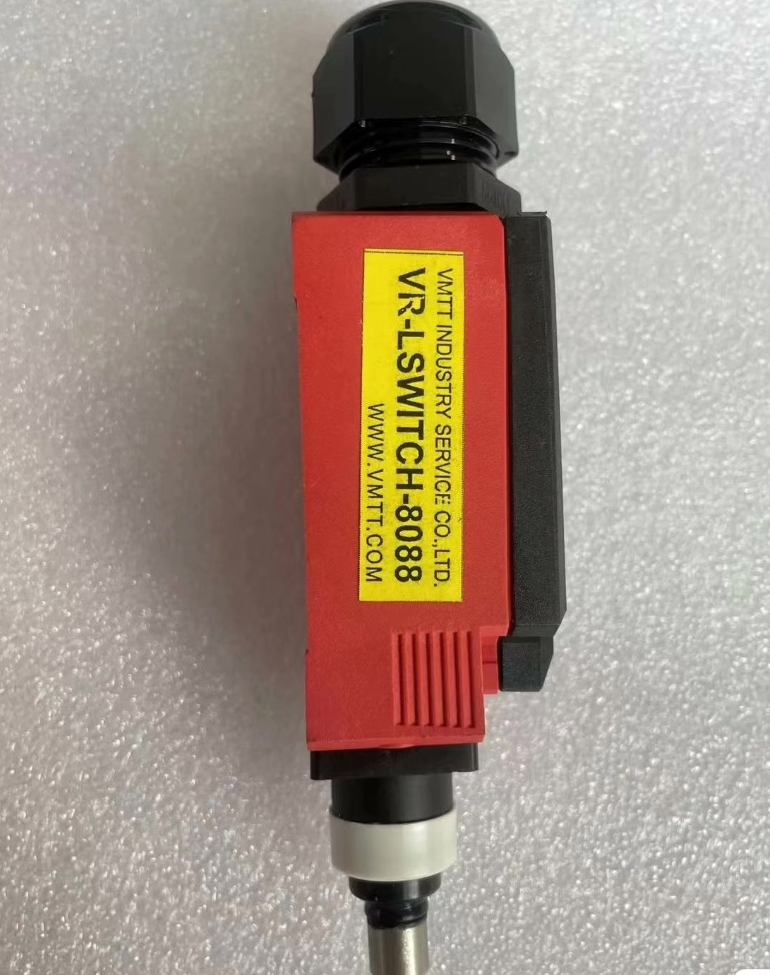

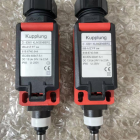
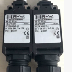
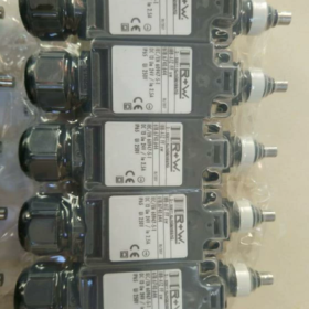
Limit Switch I88-A1ZFFSW (품목 번호. 618.6740.644)
상표: Bernstein (독일). 특별한 리미트 스위치 matched for R+W safety couplings. 618.6740.644 is the R+W material number; I88-A1Z FF SW is the Bernstein base model.
시리즈: I88 series insulated housing plunger-type travel limit switch
애플리케이션: Overload position detection for R+W SK/ES2/SL safety torque limiters / safety couplings. When overload disengagement occurs, the plunger is pushed upward to trigger the safety loop for shutdown, serving as a safety protection spare part for transmission systems.
✅ Model Definition
I88: I88 series plastic housing limit switch, compliant with DIN EN50047
A1Z: Straight plunger actuator, 1 전환 연락처 (1아니요 + 1NC). NC contact with positive opening, suitable for safety loops per IEC/EN60947-5-1
FF SW: Cable outlet version, M20 cable gland with non-removable lock cover
618.6740.644: R+W associated order item number for complete coupling spare procurement
📋 Core Electrical Specifications
정격절연전압 Ui: 250다섯
Operating voltage Ue: DC24V / AC240V
Operating current Ie: 2.5에이 (DC13); AC-15 3A
표준: IEC/EN 60947-5-1, NC contact with positive opening (safety contact)
보호 등급: IP65
하우징 재료: PA6.6 flame retardant UL94-V0
케이블 인입구: M20×1.5 cable gland
액추에이터: Plunger style, mounting head rotatable in 4×90° positions for installation adjustment
주변 온도: -30℃ ~ +80℃
기계적 수명: ≥1천만 작업
⚙️ Installation & 작동 원리
- Mounted on the side of R+W safety coupling; upon overload slip, the internal sliding ring moves axially to depress the switch plunger.
- Plunger compression triggers contact switching, sending an overload signal to PLC / safety relay to cut off drive power.
- After fault clearance and coupling reset, the plunger automatically rebounds and resets.
- 장착 구멍: M4 fixing screws, centre distance 22mm.
🛠️ Troubleshooting
- No signal output: Check plunger seizure, whether the plunger resets after coupling disengagement; inspect cable and terminal tightness.
- Contact open circuit: Positive-opening NC contact erosion due to repeated overload impact; direct replacement required.
- Water ingress & 수분: Failed sealing of M20 gland, loss of IP65; inspect cable sealing ring.
⚠️ Safety Note: This is a safety-loop component. 교체 후, overload trigger functional test must be performed to verify positive-opening contact validity.
🔁 Alternative Selection
Original unit: Bernstein I88-A1Z FF SW (R+W part no. 618.6740.644)
Same-series alternative: I88-A1Z-W (same contacts, different cable outlet; not directly interchangeable)
국내 대체: Must guarantee positive-opening safety contact + IP65 + matching plunger travel. Non-certified alternatives are not recommended for safety loops.
📌 HS Code Reference
8536500000 (Electromechanical position limit switch ≤250V)
Inspection Procedure for I88-A1ZFFSW (618.6740.644)
중요한: This switch features positive-opening safety contacts for R+W safety coupling overload protection. NC normally closed contact is the core of safety loop. For used units, continuity test alone is insufficient; positive opening function must be verified.
도구: 디지털 멀티미터 (연속성 / resistance range), 500V 절연저항계, 일자 드라이버, caliper
- Visual & 기계검사 (First Step; scrap immediately if failed)
- 주택 & 씰링
PA6.6 casing: No cracks, no aging whitening, no oil penetration; intact M20 gland thread, no hardened/missing sealing ring. Cracked housing = IP65 failure, prohibited from installation.
Nameplate: Clear marking of model I88-A1ZFFSW, no grinding or alteration.
- Plunger Actuator (Core Mechanical Component)
Press plunger steadily by hand: Smooth full travel, 달라붙지 않음, burr or hysteresis; crisp click at full stroke; full immediate rebound upon release, no half-hanging.
Measure plunger travel: Compare with new sample. Insufficient travel indicates fatigued internal spring and mechanism wear, risk of incomplete safety contact separation.
Inspect plunger surface: No indentation or deformation. R+W coupling delivers impact actuation; deformed plunger means prior heavy overload impact, internal mechanism likely damaged.
- Terminal Compartment
Open cover: Terminals free of oxidation, copper lugs without burn marks, intact screws; no accumulated water, dust or black contact powder (black powder indicates contact arcing erosion).
✅ Mechanical Pass Criteria: Smooth press & snappy rebound, no seizure; intact housing and sealing.
❌ Fail: Sticking / weak plunger rebound, cracked housing, heavy black powder inside → scrap directly; safety components shall not be repaired.
- Static Electrical Test (전원 끄기, switch removed, all terminals disconnected)
I88-A1Z: 1 changeover contact COM / NC (positive-opening safety contact) / 아니요
⚠️ Positive-opening NC serves safety loop, highest priority
- Calibrate multimeter probes in continuity range first.
- Plunger free state (unactuated)
COM ↔ NC: 전도성, resistance <0.5Ω
COM ↔ NO: open circuit OL
- Plunger fully depressed (simulate overload actuation by coupling)
COM ↔ NC: must reliably open OL (positive opening, no virtual continuity)
COM ↔ NO: 전도성, resistance <0.5Ω
Critical Failure: NC remains conductive after plunger pressed (contact welding/sticking) → safety protection disabled, strictly prohibited for use.
- Fine contact resistance test (200Ω resistance range)
Free-state COM-NC resistance: Recommended <50mΩ; >100mΩ regarded as contact aging, not recommended for safety loops. High contact resistance leads to heating and signal jitter under load.
- 절연 테스트 (500V 절연저항계, terminals vs housing)
Insulation resistance between all contact terminals and housing ≥20MΩ; lower value indicates moisture ingress and insulation degradation with leakage risk.
- Dynamic Cycling Test (Simulate repeated on-site overload cycles)
Manually actuate plunger press/release for 50 continuous cycles:
NC must reliably open every single actuation, no intermittent failure or sporadic continuity.
No signal chattering or intermittent conduction (typical symptom of pitted burnt contacts).
Safety component highlight: Many switches pass static test but NC sticks after repeated cycles. If fitted to machine, overload will not trigger shutdown, resulting in damage to the complete transmission train.
- Simulated Machine Installation Verification (선택 과목, with test bench)
- Fix the switch in the same mounting method as on R+W coupling.
- Use tooling to depress plunger to actual coupling trigger travel (do not overstroke and damage plunger).
- Connect to 24V safety loop + 안전 릴레이, trigger repeatedly to confirm reliable safety-loop cut-off.
- Comprehensive Acceptance Criteria for Used Units
✅ Permitted for installation (safety loop allowed)
Intact appearance, smooth plunger movement and strong rebound; static + 50-cycle test: NC reliably positive-opening every stroke; contact resistance <50mΩ; insulation >20MΩ.
⚠️ Only for ordinary signal circuits, prohibited for safety protection loops
Contact resistance 50~100mΩ, no welding. This model is dedicated for R+W safety coupling, not recommended for safety loops.
❌ Scrap, prohibited for all operating conditions
- Cracked housing, damaged sealing
- Plunger seizure or weak rebound
- NC contact welding (remains closed when actuated)
- Contact resistance >100mΩ
- Insufficient insulation resistance
- Intermittent continuity abnormality during dynamic test
- On-site Installation Reminders
- Even if all test items pass for used switches, complete machine overload test is mandatory to verify safety-loop action upon coupling disengagement.
- For safety-loop switches, industry practice prefers brand-new units. Used switches are only for emergency spare backup.
- 설치 후, reserve proper trigger margin for plunger to prevent false triggering or insufficient actuation caused by coupling vibration.
Inspection Notes for Positive Opening Function of Used Limit Switches
해당되는: Used safety limit switches with Positive Break / Positive Opening NC contacts, such as I88-A1ZFFSW for safety loops (R+W coupling overload protection, 안전문, torque limiters)
핵심원리: Positive opening ≠ ordinary contact switching. The mechanical linkage physically pulls NC contacts open, not relying solely on contact spring force. Even if contacts are welded together, the mechanical linkage must forcibly separate NC contacts. Static multimeter continuity test alone cannot verify positive opening.
- Pre-Inspection Requirements
- Confirm model certificate specifies positive opening
Only NC contacts marked `positive opening / positive break` on datasheet possess this function; NO contacts have no positive opening feature. NC contact of I88-A1Z is positive opening.
Ordinary travel switches without positive opening cannot replace safety switches.
- Switch must be fully detached from equipment, all wiring terminals disconnected
Never test positive opening with cables, PLC or relay circuits connected. Parasitic voltage from external circuits interferes with multimeter and causes misjudgement.
- 도구 준비
High-precision digital multimeter (연속성 + resistance range)
500V megohmmeter for insulation test
Manual tooling, only press to rated working travel; overstroke hard pressing forbidden (overstroke will damage internal positive-opening linkage. Used units already risk mechanism fatigue.)
Do not apply heavy force to hammer plunger; internal mechanical latch may be damaged, positive-opening function fails while static continuity test appears normal.
- Key Points for Static Positive Opening Test (Most Common Pitfall)
- Free state (plunger unactuated)
COM-NC conductive; COM-NO open. Record resistance value.
- Plunger pressed to actuation point (rated travel)
✅ Positive Opening Pass Criterion: COM-NC must reliably open with zero continuity
❌ Severe Hazard: Tens of ohms remaining on NC after pressing, or intermittent continuity → contacts partially welded, positive-opening mechanism failed. Safety loop will not cut off during overload.
⚠️ Trap: Minor cold welding may appear open in a single static press, but re-weld under industrial load current. Single static test is insufficient to confirm qualification.
- Do not judge only by NO contact behaviour
Normal NO contact switching ≠ valid NC positive opening. In many failed units NO switches normally while NC contacts are welded and positive-opening linkage broken; this is the most dangerous failure mode of safety loops.
- Dynamic Cycling Test (Mandatory for used units, verify mechanical reliability of positive opening)
- Reciprocating actuation for ≥50 cycles (steady press & release to simulate repeated overload shocks in field)
- Monitor NC every cycle: must open reliably on pressing and close reliably on release.
Any single occurrence of NC failure to open / intermittent continuity → reject and scrap.
- Observe tactile feedback: consistent actuation travel every stroke. If actuation travel varies, internal linkage is worn with enlarged clearance; positive-opening structure unstable.
- Optional Contact Welding Simulation Check (High-risk applications)
Used contacts may develop micro-welds: open under cold low multimeter voltage, but re-stick once heated under energized load.
Simple method: Immediately recheck NC continuity after continuous repeated actuation. If NC sticks after heat buildup, positive opening is invalid.
- 격리 & 기계검사 (Foundation of positive opening function)
- Internal visual inspection: Open terminal cover. If NC contacts show burn black spots, metal splashes or contact build-up lumps, scrap directly. Metal lumps indicate pre-welding condition which the positive-opening linkage cannot pull apart.
- Inspect drive linkage: Check plunger-driven plastic/metal lever for wear, cracking or looseness. Positive opening relies entirely on this mechanical linkage; linkage wear is the top failure mode for second-hand switches.
- 500V megohmmeter test terminal-to-housing insulation. Low insulation means internal moisture ingress, increasing risk of leakage and contact arc welding.
- Critical Safety Misconceptions
- ❌ Misconception: Multimeter continuity beep = normal.
Continuity range supplies very low voltage. Minor welded contacts may separate under weak signal but re-adhere under 24V safety loop load current, disabling positive opening.
- ❌ Misconception: Passing test means long-term fit for service.
For used safety switches: Even if all positive-opening tests pass, only temporary emergency use is permitted. Mechanical fatigue of safety components cannot be fully detected; long-term deployment in safety protection loops is not recommended.
- ❌ Misconception: Single test is enough for acceptance.
Worn positive-opening mechanisms can produce intermittent faults; multiple cycle testing is mandatory.
- Post-Installation Positive Opening Recheck
- Connect to genuine safety loop (안전 릴레이), not merely PLC digital input. Safety relays implement contact fault monitoring (contact welding detection).
- Simulate real actuation travel; neither excessive margin nor full hard stop overstroke.
- Perform complete machine overload trigger test to confirm reliable safety-loop cut-off.
- Scrap Threshold (Scrap and ban from safety loop if any condition met)
NC contact cannot open stably after actuation
NC contact surface has metal weld beads or severe arc erosion
Internal drive linkage worn, loose or cracked
Inconsistent actuation travel, unstable pressing feel
Intermittent NC sticking during dynamic cycling test
Cracked housing, damaged sealing, ingress of dust/oil inside



NH42-63-318x560.png "CHINT PC형 자동절환스위치 (ATS)NH42-63/4SZ")



