 접촉기,회로 차단기,감지기,인코더,PLC,변환기

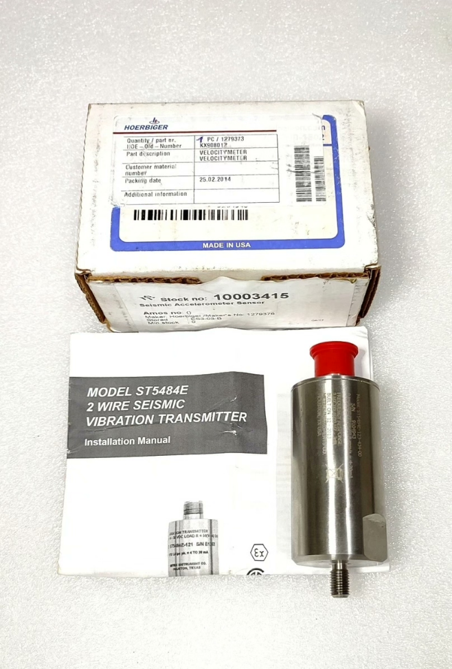

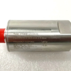
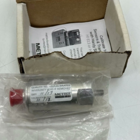
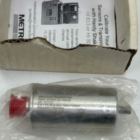
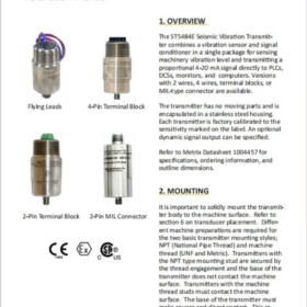
(Often mislabeled as Hoerbiger)
제품 유형: Seismic velocity vibration transmitter (2-wire 4-20mA, loop-powered). Used for vibration monitoring of bearing housings, 슬리퍼, fans and motor casings.
상표: Metrix. NOT Hoerbiger. This transmitter is frequently supplied together with Hoerbiger components in compressor packages, hence the common confusion.
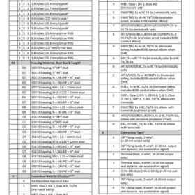
✅ Model Code Breakdown ST5484E-121-010-00
ST5484E: Series base model
121: Code for measuring range, frequency response and housing material
010: 풀 스케일 10 밀리미터/초 (RMS, vibration velocity)
00: 커넥터 / mounting option: 2-core flying lead, no auxiliary dynamic acceleration output (pure 2-wire 4-20mA)
Signal definition: 4mA = 0 밀리미터/초; 20mA = 10 mm/s RMS
📌 Key Technical Specifications
| 목 | 매개변수 |
| Measurand | Vibration velocity (RMS) |
| 범위 | 0~10 mm/s |
| 산출 | 2-wire 4~20mA, loop powered |
| 전원공급장치 | 18~28 VDC |
| 주파수 응답 | 2 헤르츠 ~ 1 kHz (standard filter for -121 암호) |
| 주택 | 303 스테인레스 스틸 (316SS optional) |
| 장착 스레드 | 1/4-28 UNF |
| 작동 온도 | -40℃ ~ +100℃ |
| 보호 | Fully potted sealed construction |
| 폭발 방지 | Ex d flameproof / Ex ia intrinsically safe available (certificate to be verified for base model) |
🧩 Applications
Vibration monitoring on bearing housings of fans, 원심 펌프, 모터, gearboxes and reciprocating compressors. 4-20mA signal connects directly to PLC/DCS AI analog input channels for vibration trending, alarm and interlock. Widely used in petrochemical, air separation and power plants.
📎 Compatible Accessories
8200 conduit elbow (mandatory for hazardous area explosion-proof installation)
7084 flange mounting adapter (thread to flat flange conversion)
Shielded twisted pair instrument cable (2-core shielded)
⚠️ Selection & 교체 노트
- 구별: ST5484E (velocity 4-20mA transmitter) vs SW5484E (version with relay switch)
- Three critical parameters to match for replacement: full scale mm/s, frequency response code, wiring configuration (with/without dynamic acceleration output)
- 국내 대안: Integrated piezoelectric vibration velocity transmitters. Explosion-proof certificate, mounting thread and frequency response curve must be matched.
📦 HS Customs Code Reference
90262090 (Transmitters for measuring / testing physical quantities such as pressure, 흐름, level and vibration)
Metrix ST5484E-121-010-00 Vibration Transmitter Troubleshooting Checklist
해당되는: 2-wire 4~20mA, 0~10mm/s RMS, ST5484E series. Three fault categories: 출력 없음, Current drift, Signal noise/jitter
Precaution for safety: Follow explosion protection rules in hazardous areas. Power off before wiring inspection. Avoid short-circuit loop tests to prevent transmitter / AI module damage.
Pre-check (Perform first for all faults)
- Verify loop power supply: 18~28VDC (measure voltage directly at transmitter terminals, not only power cabinet reading)
- Polarity check: Reversed polarity normally does not burn the 2-wire unit, but some AI modules cannot read reversed signals. 배선: + to power positive, to AI module input
- Loop total resistance check: AI module input resistance + cable resistance. Total load ≤500Ω (typical maximum load for ST5484E)
- 육안검사: Damaged housing, condensation ingress, cracked cable jacket, corroded terminals. Loose mounting thread introduces false vibration readings.
- Mounting base: Rigid mounting required. Gaskets / soft pads attenuate vibration and cause inaccurate readings. Clean rust on mating surface.
- 환경: Confirm temperature within -40~100℃. Strong cables for motors / VFDs routed in parallel nearby easily induce interference.
잘못 1: 출력 없음 (Current locked at ~0mA / below 3.8mA)
문제 해결 단계
- 전원 끄기, check loop continuity
Disconnect wiring at both ends of transmitter. Do NOT judge transmitter health by measuring resistance of piezoelectric sensor with multimeter; static resistance is not fixed.
Cable check: Open circuit in 2 signal cores; shield must not short to signal conductors.
- Standalone loop test (disconnect from DCS/PLC AI)
Simple test: 24VDC power supply in series with multimeter mA range directly connected to transmitter, bypass DCS.
Current ≈4mA: Transmitter healthy → fault on downstream DCS AI channel, terminals or scaling configuration.
Current <3.8mA or 0mA: Fault in transmitter / 전원 공급 장치 / 케이블.
- Short circuit inspection
Short between signal cores brings loop current to zero; core-to-earth short also pulls down current.
- Power voltage drop
Long cable creates voltage drop; terminal voltage below 18VDC will fail to power up transmitter.
- Transmitter hardware failure
Damaged piezoelectric element or potting water ingress. Tapping transmitter housing produces no mA change: sensor likely failed.
Quick Conclusion
✅ 4mA present in standalone 24V test: Transmitter OK, fault in AI channel or wiring
❌ Still no current in standalone test: Cable open circuit / Transmitter failure
잘못 2: Current drift (Slow gradual rise/fall, no jitter, zero offset)
징후: Static equipment, current slowly deviates from 4mA; vibration unchanged but reading creeps up or down over time
- Zero drift classification
Thermal drift: Slow offset during equipment heat-up / cool-down (inherent minor effect for piezoelectric sensors; large drift is abnormal)
Loose mounting: Unstable vibration transfer due to loose bolts; slow variation with thermal expansion. Retighten to specified torque.
- Loop load variation
Degraded AI module or oxidized terminal contact resistance changes loop voltage drop and causes mA drift; clean terminals.
- Moisture ingress inside transmitter
Seal failure, moisture on PCB. Drift worsens progressively, later accompanied by jitter or total loss of output. Focus inspection on cable entry seal.
- Incorrect DCS scaling
This model maps 0~10mm/s to 4~20mA. Wrong DCS range (예를 들어. 0~20mm/s) causes apparent reading drift while raw signal is normal.
- Mechanical resonance / base resonance
Thin weak mounting bracket resonates on stationary equipment and generates false vibration. Reinforce bracket rigidity.
- Long-term aging
Piezoelectric element aging after years of service leads to persistent zero offset.
Quick Conclusion
전원 끄기, cool down fully then restart:
Zero returns close to 4mA: Thermal effect / mounting resonance suspected
Zero remains offset: Poor terminal contact / Transmitter moisture & 노화
잘못 3: Signal noise & jitter (Fast current fluctuation, stable actual machine vibration)
징후: Stable machine vibration, random mA jumps, noisy DCS trend curve
- 방패 & 접지 (Most frequent root cause)
✅ Correct practice: Shield single-point earthed at DCS cabinet end. Shield at transmitter end must be floating. Dual-point earth creates ground loop and power frequency interference.
Shield touching signal conductors or multiple earth points is top cause of jitter.
- Cable routing
Instrument cable laid parallel with VFD / motor power cables. Separate by ≥30cm, cross at 90° where crossing required.
Use 2-core shielded instrument cable, ordinary unshielded cable is not acceptable.
- Power supply ripple
Degraded 24V DC supply with high ripple. Add filter at power side or replace regulated power supply.
- Ground potential difference (Ground loop)
Transmitter mounted on motor casing; motor frame and cabinet earth have potential difference, generating ground loop current and severe signal jitter. Isolate casing earth.
- Mechanical causes
Loose bolts, sand/rust on mating surface causing unstable sensor contact. Clean mounting face and tighten to torque.
- DCS AI filter setting
Too short AI input filter time passes interference directly to display. Increasing software filter only masks symptom; hardware interference must be resolved first.
- Transmitter hardware defect: PCB solder joint intermittency, random jitter under vibration.
Quick Conclusion
Temporarily disconnect shield earth at cabinet:
Jitter significantly reduced: Ground loop / wrong shield earthing
Jitter unchanged: Power cable interference / supply ripple / transmitter internal fault
Field Quick Test Procedure (Recommended sequence)
- Measure DC voltage at transmitter terminals (Confirm 18~28V)
- Disconnect DCS side, test transmitter with standalone 24V supply + mA meter
- Lightly tap transmitter housing and monitor mA reading:
mA rises smoothly when tapped, falls on release: Sensor basically functional
No mA response when tapped: Sensor failed
Erratic jumping on tapping: 느슨한 배선 / internal bad solder joint
- Check shield earthing and confirm single-point earth
- Check mounting bolt tightness
Fault Reference Table
| 징후 | Likely Root Cause |
| Locked at 4mA on power-up, no response to tapping | Failed sensor / Cable open circuit |
| Slow drift, more obvious with temperature change | Moisture ingress, loose mounting, excessive thermal drift |
| Fast random jitter with stable machine vibration | Dual-point shield earthing, power cable interference, ground loop |
| Current stuck at 20mA and will not reset | Shorted signal wires, 센서 손상, overload from heavy shock |
Important Cautions
- Do not apply high voltage to transmitter. Do NOT use megger to test signal cable (will damage piezoelectric element)
- This transmitter measures housing vibration, NOT shaft vibration (shaft vibration uses eddy current probes)
- For hazardous area, power down equipment before opening cover or disassembly; comply with explosion protection requirements.



NH42-63-318x560.png "CHINT PC형 자동절환스위치 (ATS)NH42-63/4SZ")



