 접촉기,회로 차단기,감지기,인코더,PLC,변환기

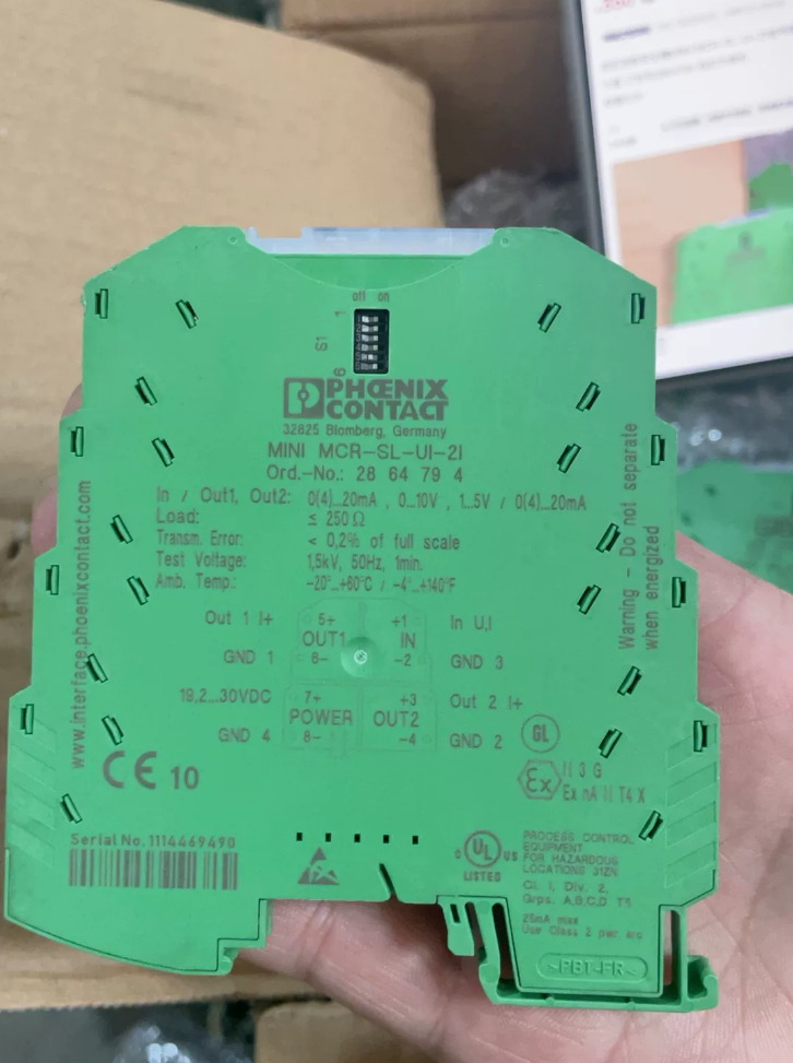

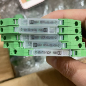
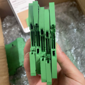
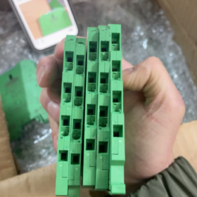
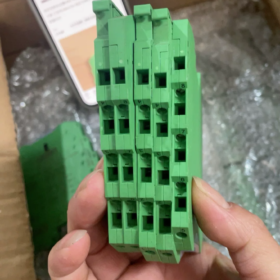
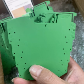
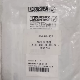
전체 모델:미니 MCR-SL-UI-2I
피닉스 접점 아날로그 신호 절연체 분배기 (신호 복제기), DIN 레일 마운트, 1-채널 입력, 2-채널 절연 전류 출력
기본정보
| 목 | 매개변수 |
| 주문 번호. | 2864794 |
| 제품 시리즈 | 미니 MCR‑SL |
| 하우징 폭 | 6.2 mm 울트라슬림 |
| 설치 | DIN‑35 레일 |
| 배선 | 나사 터미널 |
| 전원공급장치 | 24 VDC |
| 격리 | 입력-출력-전원 공급 장치 3방향 절연 |
신호 사양
입력 (DIP 스위치 구성 가능):0-20엄마 / 4-20엄마 / 0-10다섯 / 1-5다섯
2개의 독립적인 전류 출력:0-20엄마 / 4-20엄마. 2개의 출력은 PLC와 레코더 시스템의 동시 획득을 위해 상호 절연되어 있습니다..
기능:신호 분리, 1-to-2 신호 분할, 간섭 방지, 전위차 절연, 신호 변환 & 복제
정확성:일반 <0.1%
애플리케이션:송신기 신호 분할; 컨트롤러와 디스플레이에 동시에 공급되는 하나의 센서 신호 / 녹음 장치
일반적인 애플리케이션 시나리오
- AI 아날로그 루프 1-in-2-out: PLC AI 모듈과 페이퍼리스 레코더 모두에 연결된 4-20mA 센서 1개
- 접지 루프 간섭을 제거하기 위해 현장 계측기와 제어 캐비닛 간의 전위차 격리
- 6.2mm 슬림 하우징을 갖춘 컴팩트한 캐비닛에 고밀도 설치
대사 & 참조 대안
시리즈 내 교체: 입력 및 출력 유형 확인. 이 부품 번호는 더 이상 사용되지 않습니다.; 새 장치와 중고 장치 모두 시장에 나와 있습니다..
국내 상당: DIN 레일 신호 절연체 분배기, 1-인투아웃 4-20mA
문제 해결 지침
- 출력 없음: 24VDC 전원 공급 장치를 확인하십시오.; DIP 스위치 입력 범위가 필드 신호와 일치하는지 확인.
- 부정확한 출력: 루프 부하 저항 확인; 최대. 대략적인 전류 출력 부하. 500 오.
- 신호 변동: 3방향 격리의 무결성 확인; 현장 접지 상태 점검.
신호 절연체-분배기의 응용 시나리오
신호 절연체 분배기 (1-입력 다중 출력, Phoenix와 같은 일반적인 1-in-2-out 2864794 미니 MCR-SL-UI-2I). 핵심 역량: 접지 루프 억제를 위한 갈바닉 절연 + 하나의 아날로그 신호를 여러 개의 독립 출력으로 복제. 주로 산업용 4-20mA 및 0-10V 아날로그 루프에 사용됩니다..
- 다중 시스템 획득을 위한 신호 분할 (가장 일반적인)
하나의 센서 신호는 상호 영향 없이 두 세트의 장비에 신호를 공급합니다.
- 필드 송신기 (압력, 수준, 온도, 흐름, 4-20 엄마) → PLC AI 모듈에 대한 1개 채널, 다른 하나는 종이 없는 녹음기에, 디지털 표시기 또는 DCS 시스템.
- 로컬 표시기와 제어 시스템 모두에 라우팅되는 밸브 위치 피드백 신호.
아이솔레이터 스플리터 없이 직접 병렬 연결하면 신호 감쇠가 발생합니다., 장치 간의 측정 편차 및 접지 전위 충돌.
- 표류에 대한 접지 루프 간섭 억제 / 지터링 신호
현장 장비, PLC와 DCS는 별도의 접지점에 연결될 수 있습니다.. 접지점 간의 전위차로 인해 접지 루프가 생성됩니다., 결과적으로 아날로그 신호 지터 발생, 영점 드리프트 및 불안정한 판독값.
아이솔레이터 스플리터는 입력 간 갈바닉 절연을 제공합니다., 접지 루프를 차단하기 위한 출력 및 전원 공급 장치.
대표적인 산업: 대규모 생산 라인, 수처리, 야금, 긴 아날로그 신호 케이블이 있는 발전소.
- 독립 시스템 간의 신호 인터페이싱
서로 다른 제어 시스템 간의 아날로그 신호 교환:
PLC-B 및 타사 장치로 전송되는 PLC-A의 아날로그 출력, 두 시스템 모두 별도의 접지 네트워크를 갖고 있으며 공통 접지를 공유할 수 없는 경우.
메모: 표준 절연체 스플리터는 본질적으로 안전하지 않습니다.. 위험 지역 계측기 신호를 위험하지 않은 캐비닛으로 전송하려면 IS 인증 모델을 선택하세요..
- 결합된 신호 변환 & 파편
전압 입력을 다중 전류 출력으로 변환, 또는 4-20mA 입력을 다중 0-10V 출력으로 변환; 다중 채널 복제와 함께 신호 형식 변환 실현.
예: 현장 0-10V 압력 신호는 원격 획득 모듈용 2개의 4-20mA 출력으로 변환됩니다..
- 공통 모드 서지 간섭으로부터 장비 보호
아날로그 케이블이 전원 케이블과 나란히 연결되는 경우, 모터 및 VFD 스위칭으로 인해 공통 모드 간섭 및 과도 서지가 발생함. 격리로 PLC AI 카드 진입 간섭을 차단합니다., 고가의 입력 모듈을 보호하고 오류 위험을 줄입니다..
- 소형 제어 캐비닛에 고밀도 설치
Phoenix MINI 시리즈와 같은 슬림 폭 모듈 (6.2 mm) 과도한 캐비닛 공간을 차지하지 않고도 소형 캐비닛 및 캐비닛 개조를 위한 조밀한 DIN 레일 장착이 가능합니다..
- 플랜트 개조 프로젝트
기존 센서 배선을 수정하지 않고 새로운 모니터링 시스템 추가. 신호 복제를 위해 아이솔레이터 스플리터 설치; 현장 장비 교체가 필요하지 않습니다..
유사한 장치 구별
- 신호 절연체 분배기: 1-입력 다중 출력, 신호 복제 및 분할 수행
- 신호 절연체: 1-인원아웃, 격리를 제공합니다 & 신호 분할 없이 변환
- 신호 변환기: 전압-전류 변환 수행, 갈바닉 절연이 부족할 수 있으며 여러 출력을 복제할 수 없습니다.
애플리케이션 노트
- 전류 출력 채널에는 최대 부하 저항 제한이 있습니다.; 과부하로 인해 신호 왜곡이 발생함.
- 실제 입력 신호 유형과 일치하도록 DIP 스위치를 설정하십시오. (4-20 엄마 / 0-10 다섯).
- 폭발 위험 환경용, 본질 안전 인증 모델 사용; 범용 절연체 스플리터는 위험 지역 루프에 사용하면 안 됩니다..
신호 절연체-분배기의 작동 원리
피닉스를 타고 2864794 (미니 MCR-SL-UI-2I), 예를 들어 3방향 절연 1-in-2-out 절연기-스플리터.
핵심원리: 입력 간에 직접적인 전도성 연결이 없습니다., 전원 공급 장치 및 출력. 신호는 자기 또는 광커플링을 통해 전송됩니다., 하나의 원시 아날로그 신호가 여러 개의 독립적인 아날로그 출력으로 복제되는 동안.
4개의 기능 블록: 입력 컨디셔닝 → 절연 커플링 → 신호 복제 회로 → 다중 채널 출력 장치, 플러스 절연 전원 공급 장치.
- 입력 신호 컨디셔닝
필드 아날로그 신호 (4-20 엄마, 0-10 V 등) 입력 회로에 들어가다:
DIP 스위치로 신호 유형 및 측정 범위 선택.
필터 회로는 고주파 노이즈를 억제합니다.; I-V 변환은 유입 전류를 내부 전압 신호로 변환합니다..
샘플링은 입력 크기에 비례하는 내부 전압을 생성합니다..
입력 측은 후속 회로로부터 갈바닉 절연되어 있습니다..
- 절연 커플링 (코어 분리 단계)
고정밀 산업용 절연 증폭기는 대부분 자기 결합을 채택합니다. (변압기 절연), 구형 장치는 광 커플러를 사용할 수 있습니다.
조절된 아날로그 신호는 고주파 AC 반송파로 변조됩니다..
소형 절연 변압기를 통해 자기장에 의해 신호가 전송됩니다.; 1차 권선과 2차 권선 사이에 전도성 구리 경로가 없습니다..
변압기 1차측은 입력측에 속함; 2차측은 출력측에 속함. 접지 루프 경로가 차단되고 사이트 간 접지 전위 차이가 차단됩니다..
또한 전원 공급 장치는 독립 절연 변압기를 통과하여 출력측 회로에 전원을 공급합니다., 삼방향 격리 달성: 입력, 출력 및 전원 공급 장치.
⚠️ 일반 광커플러는 선형성이 좋지 않습니다.. 고정밀 MCR 시리즈는 자기 절연을 구현하여 0.1% 수준의 정밀도를 보장합니다..
- 복조 & 신호 복원
절연 장벽을 통과하는 고주파 캐리어가 복조됩니다., 원래 필드 입력과 크기가 동일한 아날로그 참조 신호 복원.
- 신호 복제 (분배기별 기능)
이 단계는 스플리터를 일반 단일 채널 아이솔레이터와 차별화합니다..
고정밀 연산 증폭기 회로는 단일 기준 신호에서 상호 독립적인 2개의 출력 드라이브 채널을 생성합니다.:
2개의 출력 채널은 서로 갈바닉 절연되어 있습니다..
각 채널은 독립적으로 다운스트림 부하를 구동합니다. (PLC, 기록계, 디지털 표시기).
한 출력의 단락 또는 오류는 다른 출력이나 원래 필드 센서 입력에 영향을 미치지 않습니다..
일반 1-in-1-out 아이솔레이터: 단 하나의 출력 드라이버 스테이지.
아이솔레이터 스플리터: 추가 다중 채널 복제 드라이버 회로.
- 다중 채널 출력 드라이버
복제된 참조 신호는 전류로 변환됩니다. (4-20 엄마 / 0-20 엄마) 또는 다운스트림 장비의 전압 출력.
전류 출력에는 최대 부하 저항 제약이 적용됩니다.; 과도한 부하 저항으로 인해 출력이 왜곡됩니다..
단순화된 요약
하나의 센서 신호를 두 개의 수신기에 직접 병렬화하는 대신 (전류 공유 오류 및 접지 전위 간섭을 유발합니다.), 아이솔레이터 스플리터는 수신 신호를 읽습니다., 필드 측에서 갈바닉 분리 제공, 내부적으로 두 개의 동일한 새로운 신호를 생성하여 두 시스템에 별도로 공급합니다.. 센서는 아이솔레이터 스플리터를 단일 부하로 구동하기만 하면 됩니다..
접지 루프 억제 원리
현장 장비는 접지점 A에 연결됩니다.; PLC는 접지점 B에 연결됩니다.. A와 B의 전위차는 수십 볼트에 이를 수 있습니다.. 직접 배선은 신호 라인에 순환 전류를 생성하고 측정 지터를 생성합니다.. 절연 변압기는 입력측 접지와 출력측 접지 사이의 전도성 경로를 차단합니다., 순환 접지 루프 전류 제거.
비교표
| 장치 | 핵심원리 |
| 신호 절연체 | 입력측 절연, 단일 출력, 신호 복제 없음 |
| 신호 절연체 분배기 | 갈바닉 절연 + 여러 개의 독립 출력을 위한 내부 신호 복제 |
| 신호 변환기 | 전압-전류 변환, 갈바닉 절연이 보장되지 않음 |
주요 내용
- 절연은 공통 모드 간섭을 억제하지만 원래 신호에 내재된 잡음을 제거할 수는 없습니다.. 전원 케이블과 별도의 아날로그 배선이 필요합니다..
- 자기 절연 모듈에는 절연 보조 전원을 위해 외부 24VDC가 필요합니다..
- 다중 채널 출력은 내부적으로 전자적으로 복제됩니다., 입력 루프의 단순한 병렬 분류가 아님.
Phoenix의 절연 전압 사양 2864794 (미니 MCR-SL-UI-2I)
4방향 격리: 입력, 출력-1, 출력 2와 전원 공급 장치가 상호 절연되어 있습니다.; EN61010에 따른 기본 절연.
| 목 | 값 | 비고 |
| 유전체 테스트 전압 | 1.5 kV AC, 50 헤르츠, 1 분 | 공장 유형 테스트; 입력-출력에 적용, 입력-전원, 출력-전원 및 두 출력 채널 사이. |
| 정격절연전압 Ui | 50 V AC/DC | 절연 장벽 전체에 허용되는 최대 연속 공통 모드 전압; 단기 테스트 전압이 아님. |
| 절연 등급 | 기초절연 | 기기 간섭 방지 전용. 개인 안전 보호용이 아님. |
현장에서 자주 오해되는 중요한 구별:
- 1.5 kV AC /1분 테스트 전압: 단기 공장 내성 테스트 값. 작동 중에 절연 장벽 전체에 1500V를 지속적으로 적용하지 마십시오..
- 정격 절연 전압 Ui =50V AC/DC: 절연 전반에 걸쳐 최대 장기 허용 공통 모드 전위차. 필드 접지 전위 차이는 50V 미만으로 유지되는 것이 좋습니다..
업계 표준 절연체-스플리터 절연-전압 비교
| 모델 유형 | 유전체 테스트 전압 | 정격 절연 전압 | 메모 |
| Phoenix MINI‑SL 시리즈 (2864794) | 1.5 kV AC /1분 | 50 V AC/DC | 울트라슬림 6.2mm, 프로세스 장비 간섭 방지를 위한 기본 절연 |
| Phoenix 차세대 MINI‑2 향상된 시리즈 | 2.5 kV AC /1분 | 300 V AC/DC | 더 큰 접지 전위차를 위한 강화된 절연 |
| 일반 가정용 절연체 분리기 | 1.5‑2kV AC/1분 | 250 V AC | 250 V는 대부분의 국내 제품의 정격 절연 전압을 나타냅니다. |
엔지니어링 응용 지침
- 이 모듈은 접지 루프 및 공통 모드 간섭만 억제하며 안전 절연 장치는 아닙니다.. 장기간 교차 절연 장벽 전위는 50V를 초과하지 않아야 합니다.. 현장 접지 전위차가 자주 50V를 초과하는 경우 절연 강화 모델을 선택하십시오..
- 1.5 kV는 단시간 내력 시험에만 적용됩니다.; 일시적인 전압 스파이크는 허용될 수 있지만 지속적인 고전압 작동은 금지됩니다..
- 4방향 격리 정의: 입력, 출력-1, 출력 2와 24V 전원 공급 장치는 쌍으로 절연되어 있습니다.. 한 출력의 단락은 다른 출력이나 입력 신호에 영향을 미치지 않습니다..
신호 아이솔레이터-스플리터의 절연 전압과 주변 온도의 관계
Phoenix를 기반으로 한 분석 2864794 미니 MCR-SL-UI-2I. 정격절연전압 차별화 (장기 운영), 유전체 내력 시험 전압 (1-분 단기 테스트), and intrinsic breakdown voltage of insulating material.
- Datasheet-published parameters are temperature-independent within rated operating range
1.5 kV AC /1 min dielectric withstand test: Performed at reference 25 °C for factory type-approval only, not operational continuous voltage.
Rated insulation voltage Ui = 50 V AC/DC: Maximum allowable continuous common-mode voltage across isolation barrier. Within full published operating temperature range (-20 °C ~ +60 °C), datasheet parameters require no temperature-derating.
✅ Apply datasheet values directly when module operates within specified temperature range. Do not arbitrarily derate Ui to a lower value merely because cabinet temperature rises to 45 °C.
- Physical mechanism: Insulating-material breakdown voltage decreases at higher temperature
Isolation is realized by insulating dielectrics inside miniature pulse transformers (polymer films, magnet-wire enamel coatings).
Rising ambient temperature increases molecular mobility inside insulation materials; intrinsic material breakdown voltage declines, and instantaneous high-voltage withstand capability drops.
Industrial modules are designed with substantial safety margin: within -20 °C ~ +60 °C, real-world breakdown margin remains far above 1500 V test level; hence datasheet does not publish derating curves.
When ambient temperature continuously exceeds maximum rated +60 °C: Insulation aging accelerates; practical withstand capability degrades significantly. Long-term over-temperature operation raises risk of isolation-barrier failure and ground-loop-suppression loss.
⚠️ Distinguish clearly: 신호 정확도 / temperature drift ≠ isolation withstand capability. Temperature-dependent measurement drift arises from signal-processing circuitry; isolation-voltage performance depends on dielectric materials, these are independent metrics.
- Temperature-dependence comparison table
| 매개변수 | Behavior within ‑20~+60 °C rated range | Condition above +60 °C over‑temperature |
| 1.5 kV AC 1 min (dielectric test) | Datasheet value unchanged; physical safety margin of insulation reduces | Instantaneous high‑voltage withstand capability drops; dielectric test may fail |
| 정격절연전압 Ui (50 V for this model) | No datasheet‑mandated derating; use full Ui rating | Insulation aging accelerates; continuous full‑Ui operation is not recommended |
| 신호 정확도 / thermal drift | Measurement error varies with temperature (tens of ppm/°C) | Measurement error further increases |
- Practical on-site engineering guidance (for MINI-SL series such as 2864794)
- Maintain module surrounding temperature between -20 °C ~ +60 °C. Within this range, apply datasheet values of 1.5 kV test withstand and 50 V rated insulation voltage without manual derating.
- If cabinet cooling is poor and module ambient temperature persistently exceeds +60 °C:
Immediate failure is not guaranteed, yet insulation aging accelerates and safety margin shrinks. Ground-loop-rejection performance deteriorates; long-term isolation-failure risk rises. Improve cabinet ventilation or adopt MINI-2 wide-temperature-range series.
- Rated insulation voltage Ui = 50 V represents a hard application limit, 온도에 관계없이. 크로스 배리어 접지 전위 차이는 50V 미만으로 유지되는 것이 좋습니다.. 현장의 접지 전위차가 정기적으로 50V에 접근하거나 초과하는 경우, 완화를 위해 냉각에 의존하지 마십시오; 더 높은 UI 모델로 업그레이드(예:. Ui=300V의 MINI MCR-2 시리즈.
- 저온 작동 (-20 ℃): 절연 내력은 부작용 없이 약간 향상됩니다..
- 일반적인 오해
❌ 오해: 캐비닛 온도 45°C에서, 1.5kV 테스트 정격은 작동 연속 전압으로 처리될 수 있습니다., 절연 장벽 전체에 1000V 허용.
✔ 교정: 1.5 kV는 단기간의 파괴적인 공장 테스트 값이므로 어떠한 온도에서도 작동 중에 지속적으로 적용해서는 안 됩니다.. 연속 서비스 조건에 대해서는 항상 정격 절연 전압 Ui를 참조하십시오..
❌ 오해: 온도가 적당히 상승할 때마다 Ui에 비례 경감 계수를 적용합니다..
✔ 교정: 제조업체가 지정한 온도 범위 내에서 전체 데이터시트 Ui 등급을 사용하세요.. 과열로 인해 단순한 산술적 경감 대신 신뢰성 수명 평가 및 열 개선이 필요합니다..
간략한 요약
데이터시트에 지정된 절연 전압 정격은 게시된 작동 온도 범위 내에서 유효하게 유지됩니다.. 물리적으로, 절연재 고전압 마진은 온도가 상승함에 따라 감소합니다., 이는 제품 설계 안전 마진으로 상쇄됩니다.. 주요 위험은 최대 정격 주변 온도를 초과하는 지속적인 작동으로 인해 발생합니다.: 절연 노화 가속화 및 절연 신뢰성 저하, 데이터시트 매개변수 번호를 직접 수정하는 대신.





NH42-63-318x560.png "CHINT PC형 자동절환스위치 (ATS)NH42-63/4SZ")



