 접촉기,회로 차단기,태양광 인버터,전기 계량기,태양 전지

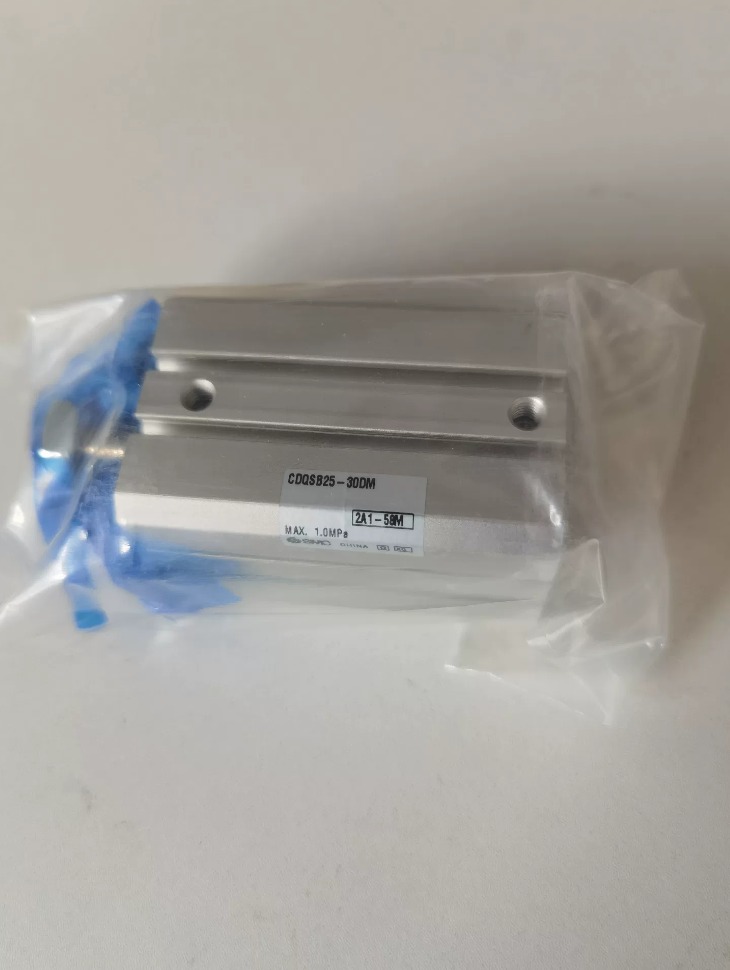

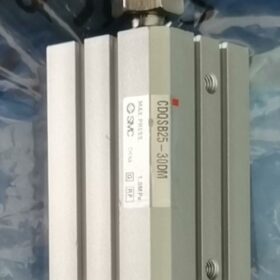
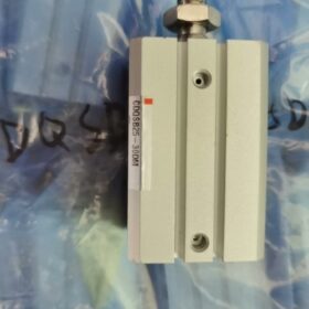
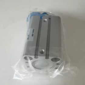
SMC CQS series compact thin cylinder, double-acting, 단일 막대, 구경 25 mm, 뇌졸중 30 mm, with built-in magnet, male thread at rod end, 표준 장착 유형. Designed for installation in confined spaces and compatible with magnetic switches.
- 모델 코드 분석 (CQDSB25-30DM)
| 암호 | 설명 |
| CQS | 시리즈: Compact thin cylinder (square body, magnetic switches mountable on multiple sides) |
| 디 | Built-in magnet (for magnetic switch installation) |
| 비 | 장착 스타일: 표준형 (through holes / female threads at both ends for general use) |
| 25 | 내경 사이즈: 25 mm |
| 30 | 뇌졸중: 30 mm |
| 디 | 작업 유형: 복동 |
| 중 | Rod end type: Male thread (standard version is female thread) |
- 주요 기술 사양
| 목 | 사양 |
| 구경 / Rod Diameter | 25 mm / 12 mm |
| 뇌졸중 | 30 mm (standard stroke) |
| 작업 유형 | 복동, 단일 막대, with built-in magnet |
| Working Fluid | 압축공기 (Non-lube) |
| 맥스. 작동 압력 | 1.0 MPa; 보증 압력: 1.5 MPa |
| 최소. 작동 압력 | 0.05 MPa |
| 온도 범위 | Without switch: -10℃ ~ 70℃; With switch: -10℃ ~ 60℃ (No icing allowed) |
| Piston Speed | 50 ~ 500 밀리미터/초 |
| Cushion | No standard cushion; Rubber cushion equipped as standard for long stroke models |
| 포트 크기 | M5×0.8 (both sides) |
| 무게 | 대략. 171 g |
- 이론적인 출력 힘 (N)
| 압력 (MPa) | Extend (안에) | Retract (밖으로) |
| 0.3 | 94 | 71 |
| 0.5 | 157 | 118 |
| 0.7 | 220 | 165 |
- Key Dimensions & 설치
설치: Standard Type B (through holes / female threads at both ends). Compatible with accessories such as foot brackets (엘), flanges (F/G) and double eye brackets (디).
Mounting Surfaces: Magnetic switches (M9 series) can be installed on four sides and port sides.
Rod End: M10×1.25 male thread (marked with M).
Allowable Side Load: Only axial force is permitted. A guiding mechanism is required if side load exists.
- 동등한 & 동일한 시리즈의 대체 모델
- CQDSB25-30D: Female thread at rod end (표준형, no suffix M)
- CDQSB25-30DM: 동일한 사양, pre-assembled with magnetic switches (예를 들어. D-M9B) at factory
- CQSK25-30DM: Anti-rotation rod (Rotation tolerance: ±0.7°)
- Repair Kit: CQSB25-PS (씰 키트)
- 애플리케이션 & 메모
응용: 자동화 장비, tooling fixtures, 전자 기기, linear push-pull motion and short-stroke positioning in narrow spaces.
메모: No built-in cushion as standard; external shock absorber is recommended for high-speed operation. Avoid side loads. No lubrication required for non-lube type.
General Installation Instructions for SMC Cylinders
- Pre-installation Inspection & 준비 (필수적인)
1.1 Model and Parameter Verification
- Verify that the cylinder model, 구경, 뇌졸중, operation type, mounting style and rod end specification conform to drawings (예를 들어. CQDSB25-30DM: 구경 25 mm, 뇌졸중 30 mm, Type B mounting, male thread rod end, built-in magnet).
- Check working pressure: The maximum operating pressure of standard SMC cylinders is 1.0 MPa and proof pressure is 1.5 MPa. Overpressure operation is strictly prohibited. The minimum actuation pressure is 0.05 MPa; conduct evaluation in advance for low-pressure working conditions.
- Lubrication type: Most SMC cylinders are non-lube type, pre-filled with long-life grease at factory. No additional lubricant is needed during normal operation.
1.2 Visual & Internal Inspection
- Check the cylinder barrel and piston rod for dents, scratches and deformation; ensure all threads are intact.
- Manually push and pull the piston rod. It shall move smoothly without sticking or abnormal noise. Do not install the cylinder if sticking occurs.
- Clean air ports and internal chamber to remove dust and metal chips, preventing seal wear.
1.3 Accessories Preparation
Prepare air tubes, quick fittings, flow control valves, magnetic switches, mounting bolts, floating joints and shock absorbers (필요에 따라) 미리.
- Installation Standards for Common SMC Mounting Styles
The second letter in SMC cylinder code stands for mounting style. Different styles have distinct stress conditions and fastening requirements. Common types (including Type B) are listed below:
| 장착 코드 | Style Name | 응용 시나리오 | Key Installation Requirements |
| 비 | Standard Through-hole Type (Through holes on both ends of body) | Compact cylinders (Mainly for CQDSB/CQSB), confined spaces | 1. Tighten four mounting bolts evenly in stages; do not fasten one side completely first. |
| 2. The cylinder mounting surface shall be fully attached to the base; no gap or tilting allowed. | |||
| 3. Only axial force is allowed; torsional force on cylinder body is forbidden. | |||
| 에프 | Front Flange (Rod-side flange) | Axial push-pull motion, front-end positioning | Ensure full contact of flange surface; tighten bolts diagonally. Avoid long-term impact load due to thin flange. |
| G | Rear Flange (Head-side flange) | Mounting on equipment backplate, rear-end positioning | Mainly subjected to tension; prevent lateral impact. |
| 엘 | Foot Bracket Mounting | Long stroke, 무거운 짐, applications requiring stable support | Use foot brackets in pairs and install lock washers for anti-loosening. Guide units are recommended at both ends for long stroke. |
| 디 | 하나의 / Double Eye Bracket Mounting | Oscillating, hinged and connecting rod transmission | Leave slight clearance between pin shaft and pin hole. Interference fit is strictly prohibited to ensure flexible swing. |
| 티 | Trunnion Mounting (Shaft seats at cylinder middle) | Long stroke and oscillating drive | Trunnion concentricity ≤ 0.1 mm. Install retaining rings on both sides to prevent axial displacement. |
Important Reminder for CQDSB Type B:
Thin Type B cylinders have low rigidity. Never bear side load or torsional force via body through holes, otherwise cylinder deformation and piston rod jamming may easily occur.
- General Requirements for Cylinder Body Fastening
3.1 Mounting Base Requirements
- The base shall be rigid and firm. Add reinforcing ribs for thin plates or suspended frames. Unstable base will cause vibration and accelerated seal damage.
- Flatness tolerance of mounting surface: ≤ 0.1 mm/m. Do not forcibly bend the cylinder to align mounting holes.
3.2 Recommended Tightening Torque for Mounting Bolts (참조)
Improper torque will lead to thread slipping or loose connection. Below are standard values for carbon steel bolts:
| 구경 (mm) | Bolt Size | Recommended Torque (Nμm) |
| 12-16 | M3 / M4 | 1.2 ~ 2.5 |
| 25 | M5 | 3.0 ~ 5.0 |
| 32 / 40 | M6 | 5.0 ~ 8.0 |
| 50 / 63 | M8 | 10 ~ 15 |
3.3 Concentricity & Parallelism
- Concentricity between piston rod movement axis and load movement axis: ≤ 0.5 mm. Larger deviation will accelerate wear of piston rod and seals.
- Keep multiple cylinders parallel for synchronous operation to avoid mutual pulling force.
3.4 Anti-loosening Measures
For vibrating and high-frequency reciprocating applications: Fit spring washers and plain washers on bolts. Apply a small amount of medium-strength thread locker for heavy vibration equipment (do not apply inside the cylinder).
- Connection between Piston Rod and Load (High-failure Area)
Suffix M of your cylinder means male thread on piston rod (standard type is female thread). Pay close attention to the following rules:
4.1 핵심원리: Radial Load, Eccentric Load and Bending Moment are Forbidden
- The cylinder is designed to withstand only axial tension and thrust. Side load and eccentric load will result in piston rod bending, guide bushing wear, air leakage and cylinder jamming.
- If slight offset or swing exists on the load, a floating joint (SMC JA series) must be installed to compensate concentricity error.
4.2 Assembly Rules for Rod End Thread
- For male thread rod end (M타입): Tighten lock nuts in stages. Do not clamp the polished surface of piston rod with wrenches or pliers, which will scratch chrome plating and cause air leakage.
- Screw in the thread to specified depth; avoid pressing against internal limit structure.
- Apply anti-loosening treatment to rod end connectors for high-frequency reciprocating operation.
4.3 Anti-rotation Requirement
If load rotation is not allowed, select anti-rotation models (예를 들어. CQSK series). Standard CQDSB has no anti-rotation structure; do not lock the piston rod with external fixtures.
4.4 Stroke Limitation
Do not use rigid mechanical stops to strike the piston rod directly at end positions. Use the cylinder’s built-in stroke limit or external shock absorbers for positioning.
- Installation of Pneumatic Circuit, Fittings & Air Tubes
5.1 포트 연결 (CQDSB25 port: M5×0.8)
- Hand-tighten port fittings fully, then turn 1/4 ~ 1/2 turn with a wrench. Excessive force will cause thread slipping or cylinder head thread cracking.
- Inlet and outlet ports are interchangeable for double-acting cylinders. For speed regulation, install flow control valves on the exhaust side (standard wiring method).
5.2 Air Tube & Piping Layout
- Select air tubes with proper inner diameter according to flow rate; use pressure-resistant tubes for long-distance routing. Reserve slack for tubes; do not pull or bend tubes during cylinder reciprocation.
- Install drain valves at low points of pipelines. Equip compressed air system with filter, regulator and lubricator (FRL unit). The lubricator can be omitted for non-lube cylinders.
5.3 Speed Regulation Rules for Flow Control Valves
- Regulation principle: Adjust speed gradually from low to high. Do not fully open the valve at one time.
- Single-direction speed control: Adjust the flow control valve on the corresponding exhaust side. Install one valve on inlet and exhaust sides respectively for two-way speed control.
- Do not fully close flow control valves under high-speed operation to prevent air pressure buildup.
5.4 Lubrication Supplement (Key for Non-lube Cylinders)
- For original non-lube cylinders: Do not add lubricant under normal working conditions. Mixed ordinary oil will damage original grease and shorten service life.
- If lubrication is required for special heavy-load or ultra-high-speed operation, only use SMC specified Turbine Oil No.1 and supply oil continuously.
- Magnetic Switch Installation (For Cylinders with Code D / Built-in Magnet, 예를 들어. CQDSB)
Cylinders marked with D have built-in piston magnets and support magnetic switches (M9B, A93, 등.), widely used for signal acquisition in automation.
- 장착 위치
Magnetic switches can be mounted on four sides of CQDSB thin cylinders. Slide the switch into sensing range after clipping into the groove, then fasten it.
Align switches with fully extended and fully retracted positions to ensure stable signal triggering.
- Fastening Requirements
Tighten screws with appropriate torque to prevent switch displacement. Add clips for reinforcement under high vibration.
- 배선 & 전기 보호
Reserve cable slack for cylinder movement; avoid tension and extrusion on cables.
Use waterproof switches for wet environments and apply waterproof treatment on wiring terminals. Separate power cables and signal cables to prevent electromagnetic interference and false triggering.
- 시운전
Manually move the cylinder back and forth to confirm stable on-off signals without poor contact or malfunction.
- Regulations for Cushioning Devices
7.1 Classification of Built-in Cushions
- Rubber Cushion: Standard configuration for short-stroke thin cylinders (CQDSB). Short cushion travel, only suitable for low speed and light load.
- Air Cushion: Standard for long-stroke cylinders. Rotate the adjustment needle: clockwise for slower movement, counterclockwise for faster movement. Adjust gradually until no impact noise occurs.
7.2 Solution for CQDSB Thin Cylinders (No Air Cushion)
This series has no built-in air cushion as standard. External hydraulic shock absorbers must be installed for high speed, heavy load and frequent impact conditions, 그렇지 않으면:
Severe operating noise and impact will occur;
Cylinder heads, threads and mounting bolts are prone to loosening and fracture under long-term impact.
7.3 Prohibited Operation
Do not rely on the rigidity of load for hard stop, which is one of the main causes of cylinder damage.
- 환경적 한계
- 온도 범위
Without magnetic switch: -10℃ ~ +70℃
With magnetic switch: -10℃ ~ +60℃ (Prevent icing at low temperature; high temperature accelerates seal aging)
- 먼지 & Moisture
Install dust covers for dusty, wet or cutting fluid environments to protect piston rod chrome plating and prevent water ingress into seals.
- Corrosion & Oil Contamination
Select stainless steel or corrosion-resistant series for acid, alkali and chemical mist environments.
- Vibration Conditions
Reinforce cylinder fastening, apply full wiring anti-loosening measures and recheck bolt torque regularly for heavily vibrating equipment.
- No-load Commissioning & Trial Operation (Final Installation Check)
- Run the cylinder without load first. Set air pressure to 0.2 ~ 0.3 MPa, switch solenoid valve manually and check smooth reciprocating motion without sticking or abnormal noise.
- Gradually raise working pressure to rated value and adjust flow control valves to target speed.
- Check all air ports, cylinder body and rod end for air leakage (Use soapy water for leakage test).
- Run 3~5 full cycles with load. Put into formal operation only after confirming normal movement, signals and limiting function.
- 엄격히 금지된 작업
- Do not drive the cylinder forcibly beyond rated pressure or rated stroke.
- Do not clamp the polished surface of piston rod with wrenches or pliers.
- Do not operate the cylinder long-term under eccentric load or side load.
- Do not bend cylinder body or piston rod forcibly to align mounting holes.
- Do not add ordinary lubricant arbitrarily to non-lube cylinders.
- Do not squeeze, pull or expose magnetic switch cables to high temperature.
- Supplementary Notes for CQDSB25-30DM Thin Cylinder
Four additional reminders for this model:
- The cylinder features thin body and low structural rigidity. Impact load, torsional load and side load on cylinder body are strictly prohibited. External guiding mechanism is mandatory for loads.
- No built-in air cushion. External shock absorber is required when speed exceeds 200 mm/s or impact exists.
- Rod end is male thread (M타입). Use lock nuts for anti-loosening during load connection; do not strike threaded parts hard.
- Short stroke (30 mm). Do not install extended connectors to avoid amplified eccentric load.


")


NH42-63-318x560.png "CHINT PC형 자동절환스위치 (ATS)NH42-63/4SZ")


