 접촉기,회로 차단기,감지기,인코더,PLC,변환기

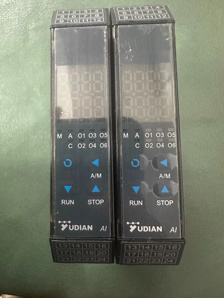

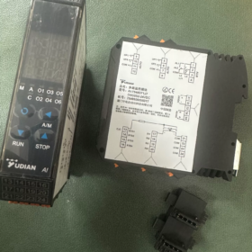
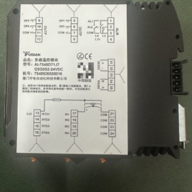
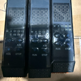
제품 유형: DIN-rail 4-channel Independent PID 온도 조절기 (AI-7xx8 Series Multi-loop Temperature Control Module)
✅ Model Breakdown
AI-7548 + D71 + J7 + G5 + G5 + S2 + -24VDC
- AI-7548: 4-loop temperature controller, 수업 0.2 정확성, 4 independent PID control loops, 5-year original manufacturer warranty; accepts 4 thermocouple/RTD inputs
- D71: DIN rail mount housing, 오직 22.5 폭이 mm, dual 7-segment digital display + front panel keys, pluggable bus terminals
- J7: Universal input board, compatible with thermocouples and RTDs (K/S/J/T/E/B/N/Pt100 etc.), 4 non-isolated input channels, built-in cold-junction compensation for thermocouples
- 1st G5: Main output module, Dual isolated SSR solid-state relay drive output, 12V/30mA (drives SSR for main temperature regulation)
- 2nd G5: Auxiliary output module, second set of dual isolated SSR voltage outputs, usable for alarm or auxiliary control
Two G5 modules provide a total of 4 SSR drive outputs, matching the 4 control loops of the AI-7548
- S2: Opto-isolated RS485 communication module, supports Yudian AIBUS and Modbus RTU protocols; connects to PLC / HMI for reading set temperature, PV/SV and alarm status
- -24VDC: Controller power supply DC24V (+10%/-15%), power consumption 5VA, not for AC220V supply
📌 Core Technical Specifications
채널: 4 independent PID loops with APID auto-tune algorithm, each channel with independent SV setting, alarm and filtering
Input signals: 케이, 에스, 아르 자형, 이자형, 제이, 티, 비, N thermocouples; Pt100 RTD
출력: 4-channel 12V/30mA isolated SSR voltage output (G5 module, for solid state relay SSR driving)
의사소통: Opto-isolated RS485, 모드버스 / AIBUS
정확성: 수업 0.2; Temperature drift ≤0.01%FS/℃
Control cycle: 0.48 에스
Operating environment: -10 ~ +60℃, humidity ≤90% non-condensing
EMC: 6kV EFT surge immunity, suitable for control cabinets, semiconductor burn-in ovens, multi-zone heating platforms, 등.
🔌 Wiring Guidelines (D71+G5 Version)
- G5 module: OP1~OP4 are output positive terminals, common COM is negative, connect externally to solid-state relays (SSR)
- 열전대: Connect positive wire to INx; all thermocouple negative wires share the common COM terminal
- 3-와이어 Pt100: Wire INx, COM and RTDx, supports 2N+1 lead compensation
- RS485: Terminals A/B, isolated bus; multiple rail-mounted units can share power and communication bus
- 전원공급장치: Never reverse the positive and negative of 24VDC
🧩 Typical Applications
Multi-zone ovens, semiconductor component burn-in testing, multi-station heating stages, multi-zone injection molding temperature control, independent temperature control for laboratory furnaces. Compact DIN rail mounting saves cabinet space.
📎 Replacement & Spare Part Information
Higher-grade alternative in same series: AI-7648D71 (수업 0.15 더 높은 정확도, 8-1년 보증)
Output modification: For 4-20mA current output, replace with X74 module; for NPN transistor output select G71
의사소통: S2 is opto-isolated RS485 module, the most common communication option for Yudian 7xx8 series for host computer connection
⚠️ Important Notes
G5 is a voltage output module. It cannot directly drive high-voltage contactors, only SSR solid-state relays. Use L-series relay modules if relay contact output is required.
그만큼 4 input channels are non-isolated between channels. Use external signal isolators if large potential differences exist between sensors.
AI-7548D71J7G5G5S2-24VDC Accuracy
Measurement Accuracy Class: 0.2
사양: ±0.2%FS ±1 digit
FS = Full Scale of the sensor
When using internal cold-junction compensation for thermocouples, an additional ±1℃ cold-junction error applies
Supplementary Parameters
- 온도 드리프트: ≤0.01%FS/℃
- Display resolution: Selectable 1℃ or 0.1℃ (only for display; internal measurement always 0.1℃)
- PID control accuracy: Determined by APID auto-tune algorithm. Steady-state temperature fluctuation is normally much smaller than instrument measurement error (affected by sensor, heating system and heat dissipation conditions)
Higher grade model AI-7648 offers Class 0.15 정확성
AI-7548 (4-channel Multi-loop Temperature Controller) Auto-tune At1~At4 Instructions
The AI-7548 features independent PID for each of the 4 채널. Each channel has dedicated auto-tune parameters: At1, At2, At3, At4 for Channel1~Channel4 respectively. Set parameter =1 to start auto-tune; parameter automatically returns to 0 after completion.
Algorithm: APID Artificial Intelligence PID (Yudian proprietary). During auto-tune, the controller performs 2~3 full on/off oscillations and automatically calculates P/I/D parameters, which are saved permanently.
✅ Preconditions for Auto-tune (비판적인)
- 배선 점검: 센서, SSR outputs and 24VDC power supply are fully functional; heating circuit can switch normally.
- 제어 모드: Set Ctrl of the corresponding channel to APID (추천) or nPID. On/Off bang-bang control cannot perform auto-tune.
- Equipment state: PV near room temperature (cold start). Do NOT start auto-tune at high steady temperature.
- SV setting: Set SV to approx. 60% of working temperature (예를 들어. target 200℃, set SV=120℃).
- Parameter lock: LOC=0 (unlocked); LOC=808 enables access to all parameters; parameters are locked when LOC>0.
📝 Front Panel Operation Steps
- Return to main PV/SV display and confirm PV reading is near ambient temperature.
- Long-press the circle confirm key for 2 seconds to enter parameter menu. Short-press confirm to scroll parameters and locate:
At1: Channel1 auto-tune
At2: Channel2 auto-tune
At3: Channel3 auto-tune
At4: Channel4 auto-tune
- Change the corresponding Atx value from 0 에게 1, press confirm to save.
- The SV window of that channel flashes At, indicating auto-tune is running.
- Wait for completion: Time depends on thermal inertia. Minutes for small heating blocks; tens of minutes for large ovens.
- When At stops flashing and Atx automatically reverts to 0 → auto-tune complete, PID parameters saved automatically.
- Change SV back to normal process temperature and put into operation.
추천: Tune channels one by one, do not launch auto-tune on all 4 channels simultaneously to avoid thermal crosstalk interference.
⏹ Manually Abort Auto-tune
Locate the corresponding Atx parameter and set value from 1 back to 0 to terminate immediately. No parameters will be saved for this aborted tuning cycle.
💻 RS485 Remote Auto-tune (Modbus/AIBUS)
Host software can write the corresponding Atx register to 1 remotely to trigger auto-tune. Register resets to 0 automatically after tuning finishes.
⚠️ Common Failures & 지침
- Never start AT at stabilized high temperature: Distorted thermal curve yields poor PID parameters, causing overshoot or oscillation.
- Keep system undisturbed during auto-tune: Do not open doors, activate forced cooling or change load.
- Retune when operating conditions change: Retune after replacing heater, 감지기, SSR or modifying oven insulation / 부하 특성.
- Minor overshoot after auto-tune: Fine-tune P/I/D manually, repeated auto-tune is unnecessary.
- At=10: Output shutoff, not used for normal auto-tune.
- G5 SSR output module: Controller outputs full amplitude to drive SSR during auto-tune. Ensure heating circuit is safe.
❓ When to Re-run Auto-tune
First commissioning after installation
After replacing thermocouple/Pt100, SSR or heating element
After modifying oven cavity or insulation structure
Large change in process set temperature
Persistent oscillation, heavy overshoot or unstable temperature control
AI-7548D71J7G5G5S2-24VDC Full Parameter Configuration Guide
AI-7548 has independent parameters for 4 채널 (CH1~CH4). Each channel has dedicated input INPx, setpoint SPx, Ctrl control mode, P/I/D, Atx auto-tune and alarm parameters. There are also global common parameters (communication Addr, bAud baud rate, LOC parameter lock, 등.).
하드웨어 구성: D71 display head, J7 universal input, dual G5 for 4 SSR outputs, S2 opto-isolated RS485, DC24V supply
- Front Panel Key Rules (D71 Display Module)
Circle Confirm Key: Long press for 2s to enter parameter menu; short press saves value and jumps to next parameter
Up/Down ▲ ▼: Modify numeric values
Left ◀: Move cursor; long press left key 2s to return previous parameter; Left + Confirm pressed together for quick exit from parameter menu
Timeout protection: 25s without keypress triggers automatic exit. Unsaved changes are discarded.
- Parameter Lock LOC (비판적인, controls parameter visibility)
LOC permission definition:
- LOC=808: Full parameter unlock, modify all channel and global parameters, used during commissioning
- LOC=0: Only EP1~EP12 defined field parameters editable (예를 들어. temperature setpoint SP), for normal production
- LOC=1: View-only for field parameters, no modification allowed
- LOC≥4: Fully locked, almost no parameters editable (communication read/write is NOT limited by LOC)
✅ Steps to unlock full parameters:
- On main PV/SV screen, long-press confirm for 2s to enter menu
- Short press confirm to scroll parameters and find LOC
- Use up/down keys to set value to 808, press confirm to save; full parameter access is now available
III. Recommended Commissioning Sequence
단계 1: Sensor Input Configuration (INP1~INP4, independent per channel)
INP = Sensor type code
K-type thermocouple → INP=0
Pt100 RTD → INP=21
제이, 티, 에스, 비, N thermocouple codes refer to manual
예: CH1 K thermocouple, INP1=0; CH2 Pt100, INP2=21
Related parameters:
dPt1~dPt4: Decimal point, 0=1℃ resolution; 1=0.1℃ display (internal measurement always 0.1℃)
SCLx/SCHx: 낮추다 / upper range limit (normally unchanged for thermocouples)
ScBx: Temperature offset correction for sensor calibration; default =0 normally
단계 2: Control Mode Ctrl1~Ctrl4 (per channel)
Ctrl=1: APID (추천, Yudian AI PID, supports At auto-tune)
Ctrl=2: nPID conventional PID
Ctrl=0: Bang-bang ON/OFF control, auto-tune At not available
This model uses G5 SSR voltage output; APID/nPID is required for continuous PID regulation
3단계: Channel Setpoint SP1~SP4
Target temperature SV for each loop. SP can be modified under LOC=0 without 808 unlock.
Step4: PID & Auto-tune At1~At4
피: Proportional band; 나: Integral time; 디: Derivative time
Atx=1: Start auto-tune of corresponding channel; controller auto-resets Atx=0 after completion
Tune channels one at a time, avoid 4-channel simultaneous AT to prevent thermal interference
Step5: Alarm Parameters (H.ALx high limit, L.ALx low limit, dHAL/dLAL deviation alarm)
H.AL: Absolute high alarm; L.AL absolute low alarm
dHAL: Positive deviation alarm (triggered when PV>SV+deviation), dLAL negative deviation alarm
AOPx: Alarm output definition, assign alarm signal to selected output channel
Step6: Global Communication Parameters (S2 RS485 Modbus/AIBUS)
Addr: Controller communication address (Modbus uses 1 address for the whole unit; AIBUS occupies 4 consecutive addresses)
bAud: 전송 속도 (2400,4800,9600,19200,38400). Host and controller baud rate must match.
S2 opto-isolated, bus wiring A/B. No duplicate Addr for multiple controllers on same bus.
- Two Configuration Methods: Panel Operation + RS485 Host Communication
방법 A: Local Setup via D71 Panel (Site Commissioning)
- 전원 켜기, verify PV display normal and no ORAL input alarm
- Long press confirm 2s to enter parameter list → Locate LOC and set to 808 for full unlock
- Configure INP1~INP4 → Ctrl1~Ctrl4 → SP1~SP4 in sequence
- Set alarm parameters H.AL, dHAL per process requirements
- Launch At1~At4 auto-tune to obtain PID values
- After commissioning, set LOC=0 to restrict editable parameters to SP and prevent accidental modification of core settings
- Press Left + Confirm together to exit menu and return to PV main screen
방법 B: Remote Configuration via Modbus RTU (PLC / PC host)
The S2 module supports Modbus RTU for remote:
Reading PV actual temperature, SV setpoint, PID parameters and alarm status
Remote modification of SP, INP, Ctrl; remote write Atx=1 to trigger auto-tune
Modbus registers start at address 40001; CH1 parameters first, CH2/3/4 follow with offset addresses. LOC lock does NOT block communication access.
- Common Parameter List (CH1 example; CH2/3/4 use same logic with suffix 2/3/4)
| 매개변수 | 설명 | Recommended Setting |
| INP1 | Sensor input type | K thermocouple=0; Pt100=21 |
| dPt1 | Display decimal point | 0=1℃; 1=0.1℃ |
| Ctrl1 | 제어 모드 | 1=APID |
| SP1 | Temperature setpoint SV | Process target temperature |
| At1 | Auto-tune | 1=Start; 0=Off |
| P1/I1/D1 | PID 매개변수 | Auto-generated by AT, fine tune manually |
| H.AL1 | Absolute high temperature alarm | Overtemperature protection threshold |
| dHAL1 | Positive deviation alarm | 예를 들어. 5 (alarm if 5℃ above SV) |
| LOC | Parameter lock | 808 for commissioning; 0 for running |
| Addr | Communication address | 1~63, unique on bus |
| bAud | 전송 속도 | 9600 흔한 |
- 일반적인 함정 & 메모
- Wrong INP setting triggers ORAL input alarm, temperature reading failure. Always verify INP first after power-up.
- Ctrl cannot be 0 (bang-bang), otherwise At auto-tune is invalid.
- G5 is SSR voltage output. No need to change OP output type to current output; cannot drive contactors directly.
- EP1~EP12: Customize visible parameters under LOC=0. 예: EP1=SP1, EP2=SP2, EP5=nonE to end list.
- Parameters only saved after confirmation. Short press confirm to save value; direct exit discards changes.
- Input channels are non-isolated. Install external signal isolators when large potential differences exist between sensors.
Ⅶ. Parameter Backup Recommendation
After full successful commissioning:
- Manually record critical parameters INP/Ctrl/PID/alarm/communication
2. Read all parameters via Modbus from host software and save project file, enabling fast parameter download for controller replacement




NH42-63-318x560.png "CHINT PC형 자동절환스위치 (ATS)NH42-63/4SZ")



