 Contactor,circuit breaker,solar inverter,electric meter,solar batteries


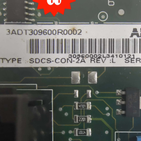
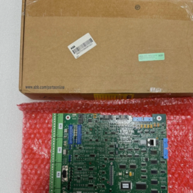
SDCS-CON-2A is a dedicated main control board for ABB DCS500 series DC drives. Below is a full specification including product overview, model breakdown, technical parameters, compatible units, auxiliary boards, replacement solutions, troubleshooting and operation regulations.
- Product Overview
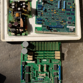
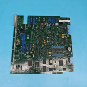
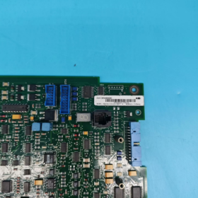
The SDCS-CON-2A serves as the core control unit of ABB industrial DC drive systems, exclusively designed for the full range of DCS500 DC drives.
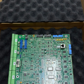
It undertakes all core functions including overall logic operation, speed/current double closed-loop control, thyristor firing pulse output, analog/digital signal processing, HMI communication and external interlock control. Known as the “brain board” of DC drives, it is a critical wearable spare part and widely applied in DC motor speed regulation for metallurgy, papermaking, crane, rolling mill and other industries.
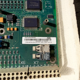
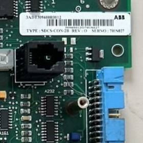
- Model Decoding
SDCS-CON-2A
- SDCS: Standard DC Drive System, ABB series identifier for DC drive systems
- CON: Control Board
- 2: Main hardware version (2nd generation main control board)
- A: Minor hardware revision / batch version identifier
- Core Technical Parameters
| Item | Specification |
| Compatible Host | Full range of ABB DCS500 DC Drives |
| Power Supply | Internal logic power of the drive: DC 24V |
| Interface Type | Analog Input/Output (AI/AO), Digital Input/Output (DI/DO), encoder interface, pulse firing output, panel communication port |
| Control Mode | DC speed regulation with speed & current double closed-loop |
| Operating Temperature | 0℃ ~ +55℃ (standard cabinet operating condition) |
| Storage Temperature | -20℃ ~ +70℃ |
| Ambient Humidity | 5%~95%RH, non-condensing, no corrosive gas |
| Mounting Type | Plug-in board, directly inserted into the motherboard slot of the drive |
| Protection Grade | Triple-proof coating, industrial dustproof and moistureproof |
- Compatible Units & Auxiliary Boards of the Same Series
4.1 Fully Compatible Drives
Full power range models: DCS500B, DCS502, DCS504, DCS506, DCS508, DCS510, DCS512, DCS514, DCS516, DCS518, DCS520
4.2 SDCS Series Auxiliary Boards (Common On-site Combinations)
| Model | Function Description |
| SDCS-CON-2A | Standard main control board (main model in service) |
| SDCS-CON-1 | Original first-generation main control board (discontinued) |
| SDCS-FEX-2A | Field control board (dedicated for DC motor field circuit) |
| SDCS-PIN-205 | Pulse interface board (cooperates with main board to output thyristor firing signals) |
| SDCS-IOB-23 | Digital/Analog I/O expansion board |
| SDCS-COM-810 | Fieldbus communication expansion board |
- Model Replacement & Compatibility
- Upgrade from Old Model
The legacy model SDCS-CON-1 (for DCS400 / early DCS500) shares identical pin definition and mounting position. SDCS-CON-2A can be used for direct replacement. Device and motor parameters need to be re-imported after replacement.
- Cross-brand Replacement
This board is custom-designed exclusively for ABB DCS500. No plug-and-play compatible third-party or domestic alternatives are available. Only original parts of the same model can be used for replacement in case of failure.
- Same-version Replacement
SDCS-CON-2A units from different batches or with suffix A are fully hardware interchangeable.
- Common Faults & Solutions
| Fault Phenomenon | Probable Cause | Step-by-Step Solutions |
| No display on drive panel, communication failure | Abnormal power supply to main board / Burnt board / Poor slot contact | 1. Cut off total power, re-insert the board and clean gold fingers; |
| 2. Measure DC24V power supply of the board; | ||
| 3. If power is normal but no response, replace the defective board directly | ||
| Fault F05 (Speed Feedback Fault) | Encoder circuit failure / Damaged signal acquisition circuit on main board | 1. Check encoder wiring and circuit continuity; |
| 2. If external circuit is normal, the acquisition channel is faulty, replace the board | ||
| No drive output, motor fails to run without fault code | Damaged pulse output circuit on main board | 1. Inspect SDCS-PIN-205 pulse board; |
| 2. If pulse board works properly, the firing circuit of main board is faulty, replace it | ||
| Frequent false overcurrent alarms, abnormal current fluctuation | Drift or damage of analog sampling circuit | 1. Calibrate current parameters; |
| 2. Replace main board if calibration fails | ||
| Board overheats and emits burning smell after power-on | Chip short circuit, high voltage intruding into low-voltage circuit | Cut off power immediately. Do not re-energize, replace the spare part directly |
- Installation, Replacement & Safety Regulations (Key Notes)
- No hot swapping: Always cut off the total power of the drive and wait for capacitor discharge before plugging or removing the board. Hot swapping will directly burn out onboard chips.
- Anti-static protection: Wear an anti-static wristband during operation. Static electricity from human body may damage precision components.
- Gold finger cleaning: Wipe pins of new or used boards with anhydrous alcohol before installation to avoid poor contact caused by oxidation.
- Parameter restoration: After installing a new main board, upload and download original device parameters, and verify motor nameplate data, field current, speed limit and closed-loop parameters. Improper parameters will lead to abnormal speed regulation.
- Ambient requirement: Regularly clean dust inside the control cabinet to prevent short circuit and poor contact caused by dust and condensation.
Combined with on-site maintenance experience of ABB DCS500 DC drives, the following guide introduces the judgment procedures for SDCS-CON-2A health status, from simple to complex, static test to dynamic test, and final verification. It distinguishes board failure from faults of external wiring, auxiliary boards and motherboard, with operational tips, judgment criteria and pitfalls highlighted for field maintenance.
- Preparations & Safety Regulations
1.1 Required Tools
Digital multimeter, anti-static wristband, anhydrous alcohol, lint-free cloth, brush.
Optional: Oscilloscope, a fully functional SDCS-CON-2A (essential for cross test).
1.2 Mandatory Safety Rules
- Disconnect the total incoming power of the drive and wait 3~5 minutes for full discharge of internal large capacitors. Never plug or unplug boards with power on.
- Wear an anti-static wristband throughout the operation to avoid chip damage from static electricity.
- Keep the working area free of oil, water vapor and dust during maintenance.
- Step 1: Power-off Static Inspection (Risk-free Preliminary Check)
2.1 Visual Inspection (Priority Check)
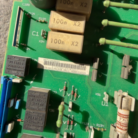
Examine the board body, gold fingers and components thoroughly. The board is confirmed defective if any of the following issues exist:
- PCB: Burnt surface, blistered or broken copper foil, detached solder pads, electrolyte leakage.
- Discrete components: Blown surface-mount fuse, bulging or leaking capacitor, discolored burnt resistors or transistors.
- Interfaces & gold fingers: Burnt pins, severely oxidized or bent gold fingers, arc marks.
- Cable sockets: Solder detachment or burn damage on pin headers for pulse board and field board connections.
> Note: Slight oxidation or dust accumulation does not mean failure. Clean gold fingers and sockets with anhydrous alcohol for recovery.
2.2 Static Electrical Measurement (Multimeter: Resistance / Diode Mode)
Mainly check for short circuit in power circuit (board supply: DC24V):
- Locate DC24V power pins (connected to motherboard). Measure resistance between 24V positive and negative terminals:
Normal: Resistance ranges from several hundred to several thousand ohms (no direct short).
Abnormal: Resistance close to 0Ω (complete short circuit) → Power circuit breakdown, board defective.
- Measure resistance to ground of all external interfaces (encoder, AI/AO, DI/DO, pulse output):
Single interface shorted: Corresponding acquisition/output channel damaged.
Multiple interfaces shorted: Main control chip damaged.
- Test onboard surface-mount fuse: Continuous conduction means normal; open circuit means board failure.
- Step 2: Isolate Peripheral Devices to Rule out False Faults
80% of on-site “board faults” are actually caused by poor contact, defective motherboard, auxiliary boards or external wiring. Isolate relevant parts first:
- Clean and re-seat: Wipe board gold fingers and motherboard slot contacts with alcohol, then firmly reinsert the board. Check for deformed or loose slot contacts.
- Disconnect all external cables: Unplug encoder cables, external DI/DO control lines, analog signal lines and communication lines to eliminate faults caused by shorted external wiring.
- Check auxiliary boards
SDCS-CON-2A works with two key auxiliary boards. Verify their status first:
SDCS-PIN-205 Pulse Board: Short circuit in pulse circuit will pull down main board signals. Temporarily disconnect its cable for testing.
SDCS-FEX-2A Field Board: Field circuit faults rarely cause main board no-response, but may trigger related alarms. Disconnect it temporarily for troubleshooting.
👉 If the fault disappears after above operations, SDCS-CON-2A is intact. Repair peripheral devices instead.
- Step 3: No-load Power-on Test (Power on drive without starting motor)
Keep external cables disconnected, then power on DCS500 and perform the following tests:
4.1 Check Board Power Supply (Prerequisite)
Use a multimeter to measure the DC24V logic power supplied by motherboard to SDCS-CON-2A.
Standard range: 22V ~ 26V
No voltage or voltage below 20V: Fault lies in drive internal power module or motherboard; main board is intact.
Voltage normal: Proceed to next test.
4.2 Onboard LED Status (Factory-defined Quick Judgment)
SDCS-CON-2A is equipped with operation indicators. Judge status by LED behavior after power-on:
| LED Status | Judgment Result |
| Normal flashing / steady on (factory default) | Basic power supply and main control chip work normally |
| No light / dim light | Onboard power module or main control chip damaged |
| Lights up momentarily then turns off | Internal short circuit or overload on the board |
4.3 HMI Panel Communication Test
The panel acts as the interactive terminal of the main board. Three typical scenarios:
- Panel completely black with no display
DC24V normal + LED off → Main board defective.
DC24V normal + LED on + no panel communication → Communication interface or drive circuit damaged.
- Panel lights up but shows fixed fault code and cannot access parameter menu
Logic unit of the board is likely abnormal. Analyze combined with fault codes.
- Panel works normally and parameters can be browsed
Basic logic, communication and main control unit are functional. Faults are likely in acquisition or output channels (proceed to functional tests).
- Step 4: Locate Fault Scope via DCS500 Fault Codes
Fault codes of DCS500 serve as accurate positioning reference to distinguish peripheral faults from SDCS-CON-2A failures:
| Fault Code | Fault Description | Fault Source Judgment |
| F01 Overcurrent | Output current exceeds limit | Check thyristors, motor and wiring first. If peripherals are normal → Current sampling circuit damaged |
| F05 Speed Feedback Fault | Abnormal encoder signal | Check encoder, wiring and shielded cable first. If peripherals are normal → Speed acquisition channel damaged |
| F22 Control Board Communication Fault | Internal communication error of main board | Main control unit of SDCS-CON-2A is basically confirmed defective |
| F31 Field Fault | Abnormal field circuit | Mostly caused by faulty FEX field board; rarely related to CON-2A |
| No fault code, motor no output and no operation | No pulse output from main board | Check PIN-205 pulse board first. If pulse board is normal → Pulse output circuit of CON-2A damaged |
| Random faults and garbled parameters | Program or storage abnormality | Aging of storage chip or main MCU on the board |
- Step 5: In-depth Test by Functional Modules (Locate Damaged Channels Precisely)
If the panel works well and no obvious physical damage is found while the equipment malfunctions, test each module one by one:
- Analog Acquisition Module
Connect standard analog signals (4-20mA / 0-10mA). Check if corresponding parameters change synchronously on the panel.
No parameter change or value drift → Analog sampling channel damaged.
- Digital DI/DO Module
Short external DI terminals and check if digital input status flips on the panel. Force DO output and measure terminal level.
No status change → Corresponding I/O channel damaged.
- Pulse Firing Output Module
Use an oscilloscope or replace SDCS-PIN-205 for testing.
If no firing pulse is output when the drive is in ready state → Pulse drive circuit of main board damaged.
- Parameter Storage Module
Modify and save any parameter. If parameters revert to original values after power cycle → Storage chip damaged.
- Step 6: Cross Swap Test (Ultimate 100% Accurate Judgment)
This is the most reliable method for on-site repair, eliminating interference from motherboard, wiring and other boards.
Test Preparation
One fully functional DCS500 drive of the same model + one verified good SDCS-CON-2A.
Test Procedures & Conclusions
- Replace the board on faulty equipment
Install the good board into the faulty drive and power on:
Equipment returns to normal → Original SDCS-CON-2A is defective.
Fault persists → Trouble lies in motherboard, thyristors, field board or wiring; main board is intact.
- Install tested board on functional equipment
Mount the suspected faulty board onto the normal drive:
The same fault recurs → Tested board is defective.
No abnormal operation → Tested board is intact; fault exists in original peripheral devices.
- Comprehensive Judgment Table for Common Phenomena
| Fault Phenomenon | Comprehensive Conclusion |
| Burnt appearance / bulging components / 24V power short circuit | Severe hardware damage, replace directly |
| 24V power normal, LED off and no panel communication | Main control core circuit damaged, replace |
| Panel works, constant F05/F01 alarms with normal encoder/current circuit peripherals | Corresponding acquisition channel damaged, replace |
| Panel works, no fault code, motor no output and pulse board normal | Pulse output circuit damaged, replace |
| Parameters lost after reboot, random garbled data and frequent false alarms | Aging storage chip or main control MCU, replace |
| Normal at cold start, faults (overheat, alarms) occur after running for a period | Poor thermal stability of components (intermittent fault), board defective |
| Fault disappears after re-insertion and gold finger cleaning | Only poor contact, board intact |
- Reminders for Frequent Misjudgments (On-site Pitfall Avoidance)
- Do not mistake motherboard faults for main board failure: Oxidized contacts or broken traces on motherboard slots present similar symptoms. Always clean the slot first.
- Do not attribute auxiliary board faults to CON-2A: Defective SDCS-PIN-205 or SDCS-FEX-2A may also cause motor stall and alarms. Replace auxiliary boards for priority testing.
- Do not ignore shorted external wiring: Shorted encoder cables or power cables will pull down board signals. Disconnect all external cables before testing.
- Slight oxidation and dust do not equal failure: Clean the board for reuse; no replacement required.


")


NH42-63-318x560.png "CHINT PC-type automatic transfer switches (ATS)NH42-63/4SZ")


