 Contactor,circuit breaker,sensor,Encoder,PLC,Converter


Model Code Breakdown
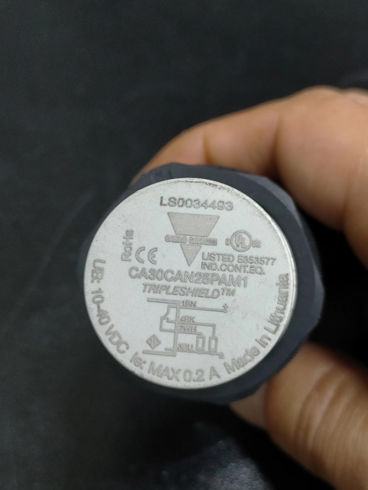
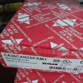
CA30CAN25PAM1
- CA: Capacitive proximity sensor series
- 30: M30 cylindrical threaded housing
- CAN: Non-shielded (non-flush mounting); CAF = Shielded (flush mountable)
- 25: Nominal sensing distance: 25 mm
- P: PNP output
- A: Dual output with NO + NC (1 normally open, 1 normally closed)
- M1: M12 4-pin male connector (cable version suffix: PA)
- Core Electrical Specifications
| Parameter | Specification |
| Supply Voltage | 10~40 VDC (including ripple) |
| Output Type | PNP, 4-wire with NO (Normally Open) + NC (Normally Closed) |
| Load Current | Max. 200 mA per channel |
| Switching Frequency | 50 Hz |
| Response Time | ≤ 10 ms |
| Hysteresis Range | 3%~20% of nominal sensing distance |
| No-Load Current | ≤ 12 mA |
| Off-State Leakage Current | ≤ 100 μA |
| Protection Functions | Full protection against reverse polarity, short circuit and transient surges |
| Sensitivity Adjustment | Multi-turn potentiometer (11 electrical turns / 16 mechanical turns), adjustable from 4 mm to 30 mm |
- Mechanical & Environmental Specifications
Housing: 30% glass fiber reinforced PBT polyester, light grey M30 thread
Ingress Protection: IP67 / IP68 / IP69K, high-pressure washdown capable (ECOLAB food-grade certified)
Operating Temperature: -30℃ ~ +85℃
Storage Temperature: -40℃ ~ +85℃
Weight: Approx. 110 g
Mounting: Non-shielded; sensing head must protrude outward, cannot be embedded in metal mounts
- LED Indicator Definition
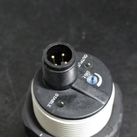
- Green LED: Steady on for stable power; flashes for dust accumulation or overtemperature fault alarm
- Yellow LED: Output status indicator (illuminates when target is detected)
- M12 4-Pin Pin Assignment (Male Standard)
- Pin 1 (Brown): DC24V Positive (+)
- Pin 2 (White): NC Normally Closed Signal
- Pin 3 (Blue): 0V GND Negative (-)
- Pin 4 (Black): NO Normally Open Signal
- Core Technical Advantages
- 4th Generation TRIPLESHIELD™ Triple Shielding Technology
Superior immunity to EMI interference from variable frequency drives and servo motors, suitable for installation near inverter control cabinets.
- Automatic Temperature & Humidity Compensation
Detection threshold does not drift under extreme temperatures or dust buildup, ensuring long-term stable performance.
- Built-In Fault Alarm
Green LED flashes when dust overload or temperature overlimit occurs, providing early warning of potential failure.
- Wide Media Compatibility
Detects metals, plastics, wood, paper, liquids and granular materials; widely used for material level and presence detection.
- Typical Application Scenarios
- Granule and powder level detection in silos / hoppers
- Carton and plastic part presence verification on packaging machines
- Material counting at washdown stations of food processing machinery
- Raw material shortage alarm for injection molding and extrusion equipment
- Position detection of non-metallic workpieces
- Cross-Series Selection Comparison
| Model | Mount Type | Sensing Distance | Output | Wiring Style |
| CA30CAN25PAM1 | Non-shielded M30 | 25 mm | PNP NO+NC | M12 plug |
| CA30CAN25PA | Non-shielded M30 | 25 mm | PNP NO+NC | 2m fixed cable |
| CA30CAN25NAM1 | Non-shielded M30 | 25 mm | NPN NO+NC | M12 plug |
| CA30CAF16PAM1 | Shielded flush M30 | 16 mm | PNP NO+NC | M12 plug |
- Mounting Prohibitions
- Do not fully embed the sensor in metal brackets; this drastically reduces sensing distance or causes complete malfunction.
- Avoid large-area metal surfaces within 30 mm surrounding the sensing face.
- Reduce sensitivity when detecting high-dielectric media (water, PVC) to prevent false triggering.
- M12 connectors with IP69K rating must be matched for washdown environments.
- Alternative Model Reference
Domestic Alternatives: M30 non-shielded 25 mm PNP NO+NC capacitive proximity sensor (e.g. Schneider XX30B1PA10M12, Omron E2K-C30MT1)
Same Brand Short-Distance Flush Model: CA30CAF16PAM1 (16 mm shielded version)
Operating Principle of Carlo Gavazzi CA30CAN25PAM1 Capacitive Proximity Sensor
- Basic Category: Capacitive Sensing (Distinct from Inductive Sensors)
This model adopts an AC high-frequency capacitive oscillation circuit. Instead of detecting eddy currents in metal, it measures changes in the dielectric constant. It can detect metals, plastics, water, paper, wood and granular powders.
Internal Core Circuit Composition
- High-frequency LC oscillation loop (resonant circuit formed by sensing electrode and internal capacitor)
- Amplitude detection & comparison circuit
- Temperature compensation and signal conditioning module
- PNP output driver and fault alarm circuit
- Complete Operating Workflow
- Unloaded Reference Oscillation State
A fixed capacitance \(C_0\) forms between the front metal sensing surface and ground. The internal LC circuit continuously generates high-frequency oscillation (MHz range) with fixed amplitude and frequency. The circuit judges “no material / no target” and maintains the original output state.
- Target Approaches & Equivalent Capacitance Changes
Air has a dielectric constant ε ≈ 1; plastics, water, wood and metals feature far higher dielectric constants.
When the measured target approaches the sensing face, the target medium fills the space between the electrode and ground, raising the overall equivalent capacitance \(C\):
\[C=\frac{\varepsilon S}{4\pi kd}\]
Reduced distance d and increased dielectric constant ε lead to higher total capacitance.
- Oscillation Amplitude Attenuation Triggers Switch Action
LC resonant frequency shifts with capacitance, increasing energy loss in the oscillation loop and significantly lowering oscillation amplitude.
The internal detection chip continuously compares the signal amplitude against a preset reference threshold. When amplitude drops below the threshold, the system confirms “target detected”, the yellow output LED illuminates, and the PNP signal flips state.
- Target Retraction & Capacitance Recovery
After the target leaves the sensing zone, the medium reverts to air, capacitance returns to the initial baseline, oscillation restores its original amplitude, and the sensor resets.
- Special Sensing Logic for Metallic Targets
Metals directly form coupling capacitance with the sensing electrode while shielding the electric field, generating a far larger capacitance variation.
At identical distances, detection sensitivity ranking: Grounded Metal > Water/Liquid > PVC Plastic > Dry Wood. The multi-turn potentiometer at the sensor tail adjusts the detection threshold to match different materials.
- Model-Exclusive Technology: Anti-Interference Principle of TRIPLESHIELD Triple Shielding
The CA30CAN25PAM1 integrates a three-layer shielding structure, the core proprietary technology of Carlo Gavazzi capacitive sensors:
- Inner Signal Shield: Wraps the sensing electrode to block high-frequency EMI from external cables, inverters and servo drives, avoiding false attenuation and false triggering of the oscillation loop.
- Temperature Compensation Layer: Built-in thermistors correct temperature drift in real time, automatically calibrating baseline capacitance under extreme hot/cold conditions to stabilize sensing distance.
- Housing Ground Shield: The M30 threaded metal housing can be grounded to block power-frequency electric field interference from cabinets and motors.
- Hysteresis Principle (Anti-Chattering Function)
The circuit features a fixed hysteresis band (3%~20% of nominal sensing distance):
Activation distance (target approaching) ≠ Reset distance (target receding)
Eliminates frequent output switching caused by minor material vibration or light dust adhesion, stabilizing material level monitoring and part counting.
- Core Differences vs. Inductive Proximity Sensors
| Feature | CA30CAN25PAM1 Capacitive Sensor | Standard Inductive Proximity Sensor |
| Sensing Principle | Dielectric constant variation + capacitive oscillation attenuation | Metal eddy current loss |
| Detectable Objects | Metals, plastics, water, powder, wood, paper | Conductive metals only |
| Sensing Distance | Up to 25 mm for M30 non-shielded type | Typically ≤15 mm for M30 inductive sensors |
| Typical Applications | Material level detection, non-metal presence check, liquid detection | Metal workpiece positioning |
- Key Principles of False Triggering (Root Cause of Mounting Restrictions)
- This CAN non-shielded model cannot be embedded in metal: metal surrounding the sensing face continuously alters baseline capacitance, locking the sensor in triggered status permanently.
- Large-area metal near the sensing face compresses the effective sensing distance by absorbing the electric field.
- High humidity and condensation increase equivalent capacitance and easily cause false triggering; sensitivity must be reduced for humid operating conditions.
Full Sensing Distance Specifications of Carlo Gavazzi CA30CAN25PAM1
- Nominal Rated Sensing Distance Sn (Factory Standard Value)
Nominal Sensing Distance: 25 mm
Test Standard: 75×75 mm, 1 mm thick grounded ST37 steel plate; the factory potentiometer is preset to maximum 25 mm by default.
The digit “25” in the model code stands for this nominal distance.
- Adjustable Sensitivity Range (Rear Multi-Turn Potentiometer)
Unified adjustable range for CAN non-shielded series: 4 mm ~ 30 mm
Minimum sensitivity trigger distance: 4 mm
Maximum adjustable upper limit: 30 mm (slightly above nominal 25 mm)
Adjustment structure: Multi-turn potentiometer with 11 electrical turns and 16 mechanical turns for threshold fine-tuning.
- Actual Effective Operating Distance Sr (Compliant with International Standard)
Per EN 60947-5-2 standard:
0.9×Sn ≤ Sr ≤ 1.1×Sn
Stable trigger distance under normal operating conditions: 22.5~27.5 mm
- Impact of Different Materials on Actual Sensing Distance (Fixed Potentiometer Setting)
Higher dielectric constant media trigger detection more easily at identical distances. Sensitivity ranking at equal distance:
Grounded Metal > Water/Liquid > PVC Plastic > Wood/Paper > Dry Air
For water and wet material detection: actual sensing distance extends significantly; lower sensitivity to avoid false triggers.
For dry wood and thin plastic detection: actual sensing distance shrinks; turn up the potentiometer to compensate.
- Critical Mounting Limitations (Directly Reduce Sensing Distance)
This model is a CAN non-shielded non-flush type:
- Large-area metal within 30 mm around the sensing face drastically shortens effective detection distance or triggers constant false signals.
- Strictly prohibit embedding the sensing head into metal brackets; electric field shielding causes sharp distance reduction or complete failure.
- Cross-Series Reference Comparison
CA30CAN25PAM1 (Non-shielded): Nominal 25 mm, adjustable 4–30 mm
CA30CAF16PAM1 (Shielded flush mount): Nominal 16 mm, adjustable 2–20 mm
Full Output Description of Carlo Gavazzi CA30CAN25PAM1
- Core Output Types
- Transistor Type: PNP (Source Output) (high-level output, signal terminal outputs +24V)
- Contact Logic: Integrated NO (Normally Open) + NC (Normally Closed) dual-channel output (4-wire sensor)
- Wiring Interface: M12 4-pin male connector (suffix M1 denotes plug version)
- Key Electrical Parameters
Max load current per channel: 200 mA DC, directly drives relays and PLC input terminals
Supply voltage: 10~40 VDC (standard 24 VDC industrial control voltage)
Output voltage drop: ≤ 2 V under 24 V @ 200 mA load
Off-state leakage current ≤ 100 μA, minimum driving load current ≥ 0.5 mA
Built-in triple protection: reverse polarity protection, output short-circuit protection, transient surge protection
- M12 4-Pin Assignment (Corresponding to Dual Outputs)
- Pin 1 (Brown): DC24V Positive Power Supply
- Pin 2 (White): NC Normally Closed Output
- Pin 3 (Blue): 0V GND Negative Power Supply
- Pin 4 (Black): NO Normally Open Output
Operation Logic
No target detected: NO open, NC closed
Target enters sensing zone: NO closed, NC open
Yellow LED illuminates synchronously to indicate triggered output status
- Model Letter Code Verification for Output Definition
CA30CAN25PAM1
P = PNP output; N = NPN output
A = Dual NO+NC output; O = NO only; C = NC only
M1 = M12 male plug wiring
- PLC Wiring Compatibility
PNP source output fits sink-type PLC inputs (PLC common terminal connected to 0V):
Connect black NO wire to PLC input terminal; the input terminal receives 24V when a target is detected for PLC ON signal recognition.
White NC wire can be wired to material shortage / no-workpiece alarm circuits.
- Same Specification Model Distinction
CA30CAN25PAM1: PNP + NO+NC + M12 plug
CA30CAN25NAM1: NPN + NO+NC + M12 plug
CA30CAN25PA: PNP + NO+NC + 2m fixed cable (no plug)
Complete Mounting Guide for Carlo Gavazzi CA30CAN25PAM1 Capacitive Proximity Sensor
- Basic Product Mounting Parameters (Core Restrictions First)
- Thread specification: M30×1.5; CAN = non-flush non-shielded (cannot be level embedded into metal plates)
- Nominal sensing distance Sn=25 mm, sensitivity adjustable from 4~30 mm (rear multi-turn potentiometer)
- Tightening torque for fixation: 4~5 N·m; violent hammering or over-tightening is forbidden to avoid damaging housing waterproof performance
- Ingress Protection: IP67/IP68/IP69K for high-pressure washdown; IP69K-rated M12 plugs must be matched for washdown applications
- Operating Temperature: -30℃~+85℃; Storage Temperature: -40℃~+85℃
- Pre-Mount Preparation
2.1 Tool List
19 mm open / ring spanner, multimeter, flat-head trimming screwdriver (for sensitivity potentiometer adjustment), straight/elbow M12 plugs, lock washers, rubber buffer gaskets (for vibrating equipment), cable ties, shielded cables.
2.2 Environment Inspection
Keep clear of strong EMI sources including variable frequency drives, servo power cables, contactors and high-power motors.
Reserve maintenance space for dust, moisture and silo operating conditions.
Ensure heat dissipation at the sensor tail in high-temperature stations; wrapping thermal insulation cotton is prohibited.
2.3 Visual Pre-Inspection
Check the sensing face for scratches, intact threads, undamaged bent pins on the M12 male connector, and no cracks or breakages on the housing.
- Mechanical Mounting Specifications (Critical, Special Requirements for Non-Flush Type)
3.1 Mandatory Mounting Rules (Metal Embedding Prohibited)
This model is non-flush non-shielded, the entire sensing face must be fully exposed:
- Metal mounting plate hole diameter ≥ 31 mm; the front sensing face must protrude at least 15 mm beyond the metal plate.
- No large-area metal surfaces within 30 mm surrounding the sensing face (steel plates, frames, metal brackets).
- Minimum clearance between sensor and adjacent metal on all sides: ≥1.2×Sn ≈30 mm.
- Flanges or metal sleeves wrapping the sensing head are strictly forbidden, as they directly shield the electric field and cause permanent false triggering or zero signal.
3.2 Spacing for Multiple Sensors Mounted Side-by-Side (Anti-Crosstalk)
When identical capacitive sensors are installed in parallel, center-to-center distance ≥ 60 mm. Insufficient spacing causes mutual interference and output signal chattering.
3.3 Target Alignment & Mounting Distance
- The sensing face must be perpendicular and aligned to the measured material/workpiece; tilt deviation ≤5°.
- Recommended stable operating distance setting: 15~20 mm (70%~80% of nominal 25 mm). Reserve margin to prevent false triggering from material thickness fluctuation and dust accumulation.
- Minimum target dimension: ≥75×75 mm (standard test steel plate size); sensing distance drops drastically for undersized targets.
3.4 Fixation Steps
- Screw the sensor in from the outer side of the mounting bracket and fit lock washers onto the thread.
- Adjust sensing head protrusion length and detection distance to target values.
- Double-nut back-clamp fixation with torque controlled at 4~5 N·m.
- Install rubber buffer gaskets on vibrating equipment to avoid thread loosening and sensing zero drift.
- M12 Plug Wiring Specifications (4-Pin Male)
4.1 Pin Assignment
Pin 1 Brown: DC24V Positive (+)
Pin 2 White: NC Normally Closed Output
Pin 3 Blue: 0V GND Negative (-)
Pin 4 Black: NO Normally Open Output
4.2 Wiring Logic (PNP Dual Output)
No target present: NO open, NC closed; yellow output LED off
Target enters sensing zone: NO closed, NC open; yellow output LED on
4.3 PLC / Load Wiring Method
PNP source output fits sink-type PLC inputs:
Connect black NO wire to PLC input terminal; PLC common terminal connected to 0V.
White NC wire may be wired to material shortage / no-workpiece alarm circuits.
Max single-channel load current: 200 mA, capable of directly driving small DC24V relays.
4.4 Wiring Anti-Interference Requirements
- Separate sensor signal cables from power and motor cables, with parallel clearance ≥30 cm; route through metal conduits for shielding if separation is impossible.
- Cable bending radius: ≥5×cable outer diameter for fixed installation; ≥10×outer diameter for moving applications. Hard bending at the M12 plug root is prohibited.
- Use shielded cables for lengths over 10 m; ground the shield layer at a single equipment end only – dual-end grounding creates circulating current interference.
- Route cables to avoid standing water; install plugs pointing downward to prevent moisture ingress into the connector.
- Sensitivity Calibration Steps (Mandatory Post-Mount Adjustment)
- Run equipment unloaded with no material in front of the sensing face.
- Insert flat screwdriver into rear potentiometer: clockwise rotation increases sensing distance; counterclockwise reduces distance (11 electrical turns, 16 mechanical turns total travel).
- Insert standard target material, slowly turn clockwise until yellow LED just illuminates, then rotate counterclockwise 2–3 turns to obtain a stable chatter-free threshold.
- For high-dielectric media (water, PVC, wet powder): drastically reduce sensitivity to eliminate continuous false triggering from condensation or material buildup.
- For low-dielectric materials such as dry wood and thin cardboard: moderately raise sensitivity to compensate for reduced detection range.
- Complete multiple forward/retraction tests post-calibration; pass if no frequent LED flickering or signal chattering occurs.
- LED Status Explanation (Judgment Reference for Mounting & Commissioning)
- Green LED: Steady on = normal power supply; flashing = dust overload or overtemperature fault alarm
- Yellow LED: Output status lamp, illuminated when material is detected
- Both green and yellow LEDs steady on simultaneously: Optimal sensing distance setting with no critical zone chattering
- Strict Mounting Taboos (Forbidden Operations)
- ❌ Flush embedding into metal plates or wrapping sensing head with metal sleeves
- ❌ Large metal frames or angle iron placed close to the sensing face
- ❌ Over-torque clamping or hammering sensor housing (destroys IP waterproof rating)
- ❌ Signal cables routed in the same conduit as inverter and servo cables with short clearance
- ❌ Adjust sensing distance to maximum limit of 30 mm (prone to false triggering from dust and material residue)
- ❌ M12 plugs installed pointing upward (water accumulates inside connector and causes short circuit)
- ❌ Parallel installation of multiple sensors with center spacing <60 mm
- ❌ Wrapping thermal insulation materials around sensor in high-temperature environments (triggers overheat alarm)
- Supplementary Mounting Tips for Washdown / Silo Special Conditions
- Food washdown environments: Adopt IP69K-rated elbow M12 plugs; inspect plug waterproof gaskets after every cleaning cycle.
- Powder silo level detection: Mount sensor tilted downward to minimize direct dust accumulation on the sensing face. Regularly wipe surface dust – frequent green LED flashing indicates excessive dust buildup.
- High-humidity / condensation conditions: Reduce sensitivity by 30%~50% to prevent continuous sensor triggering by water mist.
- Power-On Acceptance Procedure Post-Mounting
- Cut power and double-check pin wiring to eliminate short circuits and reverse polarity.
- Power on and verify steady green power LED with no fault flashing.
- Insert and retract target material repeatedly; yellow LED switches smoothly without strobing.
- Measure NO/NC output voltage with multimeter to confirm normal state switching between unloaded and target-present conditions.
- Continuous 30-minute operation test with zero false triggering and no alarms = mounting & commissioning completed.





NH42-63-318x560.png "CHINT PC-type automatic transfer switches (ATS)NH42-63/4SZ")



