 Contactor,circuit breaker,solar inverter,electric meter,solar batteries

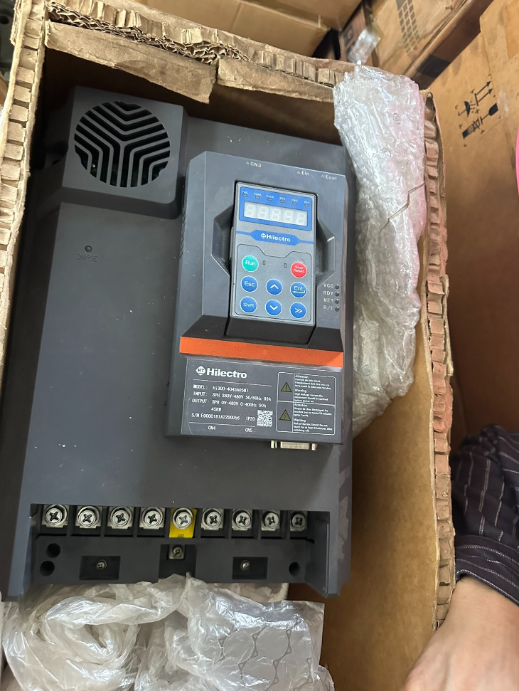

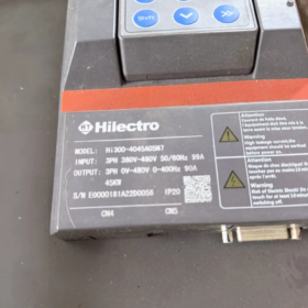
It is a standard medium-and-high-power AC servo drive of the Hi300 series manufactured by Ningbo Haitian Drive (Brand: Hilectro). As the flagship model of Haitian Drive for electro-hydraulic servo applications, it is widely compatible with industrial equipment such as injection molding machines and hydraulic presses. It features high reliability, superior energy efficiency and precise pressure/speed control performance. Matched with 45kW permanent magnet servo motors, it adopts forced air cooling design and supports multiple encoder types as well as industrial bus expansion.
Bit-by-bit Model Code Decoding
Per the official naming specification, each segment of the model Hi300-4045A05N7 is defined as follows:
| Code Segment | Definition | Detailed Description |
| Hi300 | Product Series | Standard general-purpose servo drive equipped with Hi3-S1 control board, designed for universal electro-hydraulic servo scenarios |
| 4 | Voltage Class | 3-phase 380V~480V AC, compatible with industrial 3-phase power grid |
| 45 | Power Rating | Maximum matching power of servo motor: 45kW |
| A | Hardware Version | 1st-generation standard hardware version |
| 0 | Cooling Mode | Forced air cooling |
| 5 | Chassis Code | No.5 standard chassis, covering power range of 37~45kW |
| N | Configuration Type | Standard basic configuration without special customized functions |
| 7 | Main Control Chip | Equipped with DSP28377 main control chip |
Core Technical Specifications
Electrical Specifications
| Category | Item | Specification Value |
| Input Side | Rated Voltage | 3-phase 380V~480V AC |
| Rated Frequency | 50/60Hz | |
| Voltage Fluctuation Range | -15% ~ +10% | |
| Frequency Fluctuation Range | ±5% | |
| Rated Input Current | 99A | |
| Matching Power Supply Capacity | 83kVA | |
| Output Side | Rated Matching Motor Power | 45kW |
| Rated Output Capacity | 63kVA | |
| Rated Output Current | 90A | |
| Overload Capacity | 150% rated current for 60s; 200% rated current for 1s (at switching frequency of 2kHz) | |
| Maximum Output Voltage | 3-phase 380~480V (follows input voltage) | |
| Maximum Output Frequency | 400Hz |
Control & Interfaces
Supported Encoders: Resolver, incremental TTL encoder, sine/cosine encoder; expandable to absolute encoder, Endat encoder
Standard Interfaces: CAN bus, RS485 (Modbus protocol supported), high-speed Ethernet debugging port, USB port (parameter read/write via USB flash drive)
Control Modes: Closed-loop speed control, closed-loop pressure control, closed-loop torque control; compound pressure/flow control for electro-hydraulic servo systems
Expandable Functions: PROFINET bus module, STO Safe Torque Off, WIFI wireless operator panel
Mechanical & Environmental Specifications
| Item | Specification Value |
| Cooling Mode | Forced air cooling |
| Chassis Standard | No.5 standard chassis |
| Overall Weight | 11.3kg (Standard Version) / 16.2kg (Sheet Metal Version) |
| Mounting Method | Vertical wall mounting, side-by-side installation supported |
| Operating Ambient Temperature | -10℃ ~ +40℃ (Derating operation required above 40℃) |
| Protection Class | IP20 |
| Switching Frequency | Default 4kHz, adjustable range 2~8kHz (Derating required for high-frequency operation) |
Hi300 Series No.5 Chassis Models (Air-cooled Type)
| Full Model | Matching Power | Chassis Standard | Cooling Mode |
| Hi300-4037A05N* | 37kW | No.5 | Air cooling |
| Hi300-4045A05N* | 45kW | No.5 | Air cooling |
Note: The suffix represents function version code, replaceable with D (Resolver Encoder Card), P (PROFINET Card), T (STO Safety Function) and other customized versions.
Typical Application Scenarios
- Injection Molding Machine Industry: Energy-saving retrofits of electro-hydraulic servo systems for horizontal/vertical injection molding machines, supporting new machine assembly; achieves precise pressure and flow control with energy saving rate up to 30%~80%.
- Hydraulic Forming Equipment: Servo power systems for die casting machines, aluminum extrusion presses, hydraulic oil presses and hydraulic punching machines.
- General Hydraulic Power Units: Energy efficiency upgrade for industrial hydraulic systems, electrification retrofits of construction machinery hydraulic stations.
- Other Scenarios: Electric drive systems for off-road mobile machinery, large material conveying equipment.
Common Fault Troubleshooting Matrix
| Fault Code | Fault Phenomenon | Inspection & Solutions |
| Er049 / Er055 | DC Bus Overvoltage | 1. Check if input grid voltage is excessively high; 2. Inspect braking resistor wiring and resistance matching; 3. Extend deceleration time to reduce regenerative energy. |
| Er050 / Er056 | Drive Overcurrent | 1. Check U/V/W output wiring for short circuit or grounding fault; 2. Test motor insulation integrity; 3. Confirm whether load is locked or suffers abrupt load change. |
| Er054 | Heatsink Overheat | 1. Verify normal operation of cooling fan; 2. Clean dust inside air duct to ensure smooth ventilation; 3. Lower ambient temperature or operate under derating condition. |
| Er083 | Encoder Fault | 1. Check encoder cable connection and shielding grounding; 2. Inspect encoder connector for looseness or water intrusion; 3. Verify damage of encoder body. |
| Er144 | Drive Overload | 1. Verify power matching between motor and drive; 2. Check long-term overload condition of load; 3. Optimize acceleration/deceleration curve to mitigate impact load. |
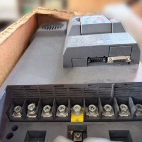
- Complete Terminal Definition (Hi300-4045A05N7 No.5 Air-cooled Model)
- Main Power Circuit Terminals
Located in the high-power zone at the bottom of the drive, matched for 45kW power class, wiring specifications and functions as follows:
| Terminal Mark | Terminal Name | Function Description | Wiring Requirements |
| R, S, T | Main Power Input | 3-phase 380V~480V AC power input, 50/60Hz | 25mm² copper cable recommended; equip with 125A molded case circuit breaker at front end. |
| U, V, W | Motor Power Output | Connect to 3-phase power windings of servo motor | 25mm² copper cable recommended, phase sequence must correspond one-to-one with motor. |
| PE | Protective Earth | Safety grounding terminal of drive | Ground resistance ≤10Ω, wire cross-section ≥16mm², single-point reliable connection to cabinet earth bar. |
| P+, BR | Braking Resistor Interface | External braking resistor to absorb regenerative energy during deceleration | Standard recommendation for 45kW unit: 16Ω / 10kW power braking resistor. |
| P1, P+ | DC Reactor Interface | External DC reactor to mitigate grid harmonic distortion | Short-circuit copper bar installed at factory; do not remove without special requirements. |
- Control Terminals of Hi3-S1 Control Board
Located in the front control zone of the drive, including four types of interfaces: I/O, analog, communication and encoder.
(1) Digital Input Terminals (X1~X6, NPN Common Cathode Type)
| Terminal No. | Default Function | Signal Type | Explanation |
| X1 | Servo Enable (SON) | DI Input | Short-circuit with COM to set drive to enable ready state. |
| X2 | Fault Reset (RST) | DI Input | Clear resettable fault alarms when conducting. |
| X3 | External Run Trigger | DI Input | Trigger motor operation via external contact under panel mode. |
| X4~X6 | Programmable Reserve | DI Input | Configurable via parameters for multi-stage pressure/flow switching and other functions. |
| COM | Digital Input Common Terminal | 0V Common | Connect to negative pole of external 24V power supply. |
| +24V | Auxiliary Power Output | 24V DC Output | Maximum load capacity 200mA, power supply for external low-power sensors. |
(2) Digital Output Terminals (Y1~Y3, Relay Contact Output)
| Terminal No. | Default Function | Contact Rating | Explanation |
| Y1 | Fault Alarm (ALM) | AC250V/1A | Normally open contact closes when drive faults, open under normal standby. |
| Y2 | Running Status | AC250V/1A | Contact closes during motor operation, opens at standby. |
| Y3 | Speed Reached | AC250V/1A | Customizable via parameters for pressure reached, overload warning and other functions. |
(3) Analog Interfaces (Core Control Ports for Electro-Hydraulic Servo)
| Terminal No. | Function | Signal Type | Corresponding Application |
| AI1 | Flow Command Input | 0~10V / 4~20mA configurable | Corresponding to pump flow / motor speed reference. |
| AI2 | Pressure Command Input | 0~10V / 4~20mA configurable | Corresponding to closed-loop pressure reference of hydraulic system. |
| GND | Analog Common Ground | 0V | Reference ground for analog signals, single-point connection with control ground required. |
| AO1 | Monitor Output 1 | 0~10V | Configurable to output actual current, speed, pressure feedback values. |
| AO2 | Monitor Output 2 | 0~10V | Configurable to output DC bus voltage, heatsink temperature, etc. |
(4) Communication & Encoder Interfaces
Communication Interfaces: Standard CAN bus (CAN_H/CAN_L/GND), RS485 (Modbus-RTU supported), RJ45 Ethernet debugging port, USB-A port (parameter backup / firmware upgrade via USB flash drive)
Encoder Interface (CN2): Standard resolver interface (Excitation ±, Sine ±, Cosine ±, Shield Ground); expandable to TTL incremental encoder, sine/cosine encoder, absolute encoder card.
- Wiring Forbidden Rules (Strictly Prohibited Operations)
- It is strictly forbidden to connect main power terminals R/S/T to motor output terminals U/V/W, which will burn out IGBT power modules instantly.
- Do not short-circuit P+ and BR terminals; never connect braking resistor directly across positive and negative poles of DC bus, which may cause fire hazards.
- Do not plug/unplug encoder cables and control terminal blocks under live power, which may damage communication chips of interfaces.
- PE terminal shall never be connected to grid neutral wire; it must be separately wired to equipment protective earth bar.
- Do not touch main circuit terminals within 5 minutes after power-off, as DC bus capacitors store high residual voltage.
- Quick Commissioning Guide (Electro-Hydraulic Servo / Injection Molding Machine Scenarios)
The following steps apply to hydraulic systems equipped with resolver permanent magnet servo motors and firmware version V6.30 or above.
- Pre-power-on Safety Inspection
- Confirm tight wiring of main circuit, control circuit and encoder without short circuit, misconnection or loose contact.
- Fully loosen the relief valve of hydraulic system to ensure motor operates under no-load condition after startup.
- Disconnect external enable signal (X1) to prevent automatic drive operation after power-on.
- Measure grid input voltage with multimeter to verify it falls within the range of 380V±15%.
- Factory Reset & Permission Unlock
- After power-on, the drive enters standby state with initial interface displayed on panel.
- Press down key twice consecutively to enter USB120 permission interface, input password 1000 to complete unlock; the interface automatically switches to USB121 after successful unlock.
- Access quick parameter group SP.02, set value to 2 and press Ent to confirm; the drive executes factory parameter reset.
- The drive restarts automatically after reset completion; wait until standby interface resumes.
- Motor Parameter Matching & Loading
- Check model code on nameplate of matched Haitian servo motor (the drive has built-in parameter library for full series of Haitian motors).
- Enter parameter SP.01 and input corresponding motor model code (standard code for 45kW injection molding servo motor is subject to motor nameplate).
- Re-enter SP.02, set value to 20 and press Ent to confirm; the drive automatically loads rated motor parameters.
- The panel displays Bu002 during loading process, and returns to standby interface automatically upon completion.
- Encoder Zero Offset Auto-tuning (Core Step)
> The motor must stay no-load and relief valve fully loosened; otherwise angle calibration will be inaccurate.
- Enter parameter SP.03, set value to 1212 and press Ent to confirm.
- Short-circuit servo enable (conduct X1 and COM), press green RUN key on panel.
- Panel shows Bu001, the motor rotates slowly for approximately one revolution to finish encoder zero offset calibration automatically.
- Current encoder angle value displays after successful tuning; repeat operation 2~3 times, qualified if angle deviation ≤0.5°.
- If fault Er068 (Initial Angle Error) occurs: change parameter CS.04 from 0 to 1, or swap any two phases of U/V/W after power-off and re-run auto-tuning.
- No-load Jog Test Run
- Enter parameter SP.11, set test speed to 20 (Unit: r/min).
- Keep enable signal conducting and press RUN key to observe motor rotation direction.
- Direction judgment standard: clockwise rotation is forward when viewing from motor tail towards oil pump; re-run auto-tuning if reverse rotation occurs.
- Press STOP to halt operation, gradually increase speed to 100r/min and run no-load for 3 minutes, confirm no abnormal noise, vibration or overheating.
- Closed-loop Pressure & Flow Calibration
- Flow Calibration: Input full-scale 10V signal to AI1, adjust SP.20 (Flow Gain) to make motor speed reach rated value.
- Pressure Calibration: Close stop valve at pump outlet, input full-scale 10V signal to AI2, adjust SP.21 (Pressure Gain) to make system pressure reach maximum rated value.
- Tune SP.22 (Flow Loop Integral Time) and SP.23 (Pressure Loop Integral Time) to optimize response speed and eliminate system oscillation.
- Test pressure/flow commands at 25%, 50%, 75% and 100% ranges step by step, confirm deviation between feedback and command ≤2%.
- Parameter Saving & Load Joint Commissioning
- After all parameters are debugged, enter SP.00 and set value to 1 to permanently save parameters into the drive.
- Connect to main control system of injection molding machine, conduct cyclic tests in manual, semi-automatic and full-automatic modes sequentially.
- Real-time monitor operating current, DC bus voltage and heatsink temperature to ensure no alarms or overload conditions.
- Fine-tune acceleration/deceleration time and pressure loop bandwidth according to process requirements to match equipment production cycle.
Hi308-4045A05N7 is the official upgraded successor model of Hi300-4045A05N7
Both models adopt 45kW 3-phase 380V air-cooled No.5 chassis, with basically compatible core power parameters, mounting dimensions and terminal definitions for direct physical replacement. However, Hi308 achieves comprehensive upgrades in control algorithm, interface expandability, environmental adaptability and functional richness, suitable for more complex mid-to-high-end electro-hydraulic servo applications.
Core Comparison Table (Same 45kW No.5 Air-cooled Chassis Models)
| Comparison Item | Hi300-4045A05N7 | Hi308-4045A05N7 |
| Product Positioning | 1st-generation standard electro-hydraulic servo drive, basic general model | 2nd-generation optimized high-performance general model, official replacement upgrade of Hi300 |
| Hardware Platform | 1st-gen Hi3-S1 control board with DSP28377 main controller | Optimized Hi3-S1 control board with identical main chip; upgraded peripheral sampling and drive circuits for higher computing efficiency and anti-interference performance |
| Rated Output Current | 90A | 90A (Fully compatible power parameters, directly matched with same-spec motors) |
| Rated Input Current | 99A | 92A (Optimized overall efficiency, lower grid-side loss and superior energy-saving performance) |
| Overload Capacity | 150% rated current for 60s; 200% rated current for 1s (only valid at 2kHz switching frequency) | 150% rated current for 60s; 200% rated current for 1s (supported for full frequency band above 5Hz, full rated output at 4kHz switching frequency) |
| Switching Frequency Performance | Default 4kHz, adjustable 2~8kHz; heavy derating required for high-frequency operation | Default 4kHz, adjustable 2~8kHz; drastically reduced derating demand at high frequency via upgraded cooling structure |
| Control Algorithm | Basic compound pressure/flow closed-loop control with single fixed set of PID parameters | Optimized current loop, speed loop and pressure loop control algorithms; supports multi-stage PID switching, precise minimum flow/pressure setting and improved pressure relief effect; pressure control accuracy improved by approx. 30% |
| Dedicated Hydraulic Functions | Only basic single-pump control supported | Newly added parallel servo pump confluence control, SPM/IPM motor parameter auto-tuning, adaptive load compensation; compatible with multi-pump systems and complex hydraulic processes |
| Dynamic Response | Standard grade; approx. 30ms no-load acceleration from 0 to 2000rpm | High-response grade; approx. 25ms no-load acceleration from 0 to 2000rpm; pressure step response speed increased by 20% |
| Standard Interfaces | CAN bus, RS485, Ethernet debug port, USB flash drive port, resolver encoder interface | Retains all basic interfaces; newly adds hardware STO Safe Torque Off interface and native motor temperature detection (KTY/PTC) support |
| Expansion Capability | Partial versions expandable with TTL encoder, PROFINET and STO with limited compatibility | All versions support expansion of TTL encoder, sine/cosine encoder, absolute encoder, PROFINET bus and programmable LCD operator panel with complete expansion ecosystem |
| Communication Protocols | Basic Modbus-RTU, proprietary CAN protocol | Fully compatible with all basic protocols, newly supports Modbus-TCP; deeply optimized PROFINET protocol for easier connection with upper controllers and production line systems |
| Overall Weight | 11.3kg (Standard) / 16.2kg (Sheet Metal) | 17.6kg (Strengthened structure and upgraded cooling fins for enhanced overall heat dissipation) |
| Operating Ambient Temperature | -10℃ ~ +40℃, derating required above 40℃ | -10℃ ~ +45℃, derating required above 45℃ with stronger adaptability to high-temperature workshops |
| Mounting Requirements | 200mm heat dissipation clearance required top and bottom; gaps needed for side-by-side installation | Optimized air duct design for lower temperature rise under identical load, better compatibility for side-by-side mounting and flexible cabinet layout |
| Firmware System | V6.21 and earlier versions, original parameter architecture | V6.30 and above, backward-compatible parameter system with dozens of newly added debugging and protection parameters |
| Debug Functions | Basic encoder auto-tuning, manual pressure/flow calibration | New one-click auto-calibration, self-diagnosis for faults and running data waveform recording, improving debugging efficiency and fault troubleshooting capability |
| Protection Mechanism | Basic protections against overvoltage, overcurrent, overheat and encoder faults | Newly added IGBT junction temperature prediction, motor overload pre-alarm and grid quality monitoring with expanded protection coverage |
| Typical Applicable Scenarios | Conventional injection molding machines, energy-saving retrofits of simple hydraulic stations, low-performance-demand applications | High-speed injection molding machines, die casting machines, hydraulic oil presses, multi-pump confluence systems, high-temperature workshops and other mid-to-high-end electro-hydraulic servo applications |
Supplementary Explanations
- Replacement Compatibility
The two models share identical cabinet mounting hole positions, main circuit terminals and control terminal definitions. Hi308 can physically replace Hi300 directly without cabinet hole modification or main circuit wiring changes. Core parameters can be migrated directly; only minor tuning of optimized PID parameters is needed for normal operation.
- Model Selection Suggestions
For maintenance of existing equipment and cost-sensitive ordinary retrofit projects, Hi300 meets basic operating requirements.
For new machine assembly, high-precision process demands, multi-pump systems and high-temperature operating environments, the upgraded Hi308 is preferred for superior long-term stability and performance margin.


 series. It is a standard model with 200V voltage class, matching 2kW-class servo motors. Equipped with dual command interfaces of pulse train and analog voltage, it supports full-mode control including position,")
. It is a mid-range CPU with outstanding cost performance in the S7-1200 product line. Integrated with native digital I/O and analog inputs")


")
NH42-63-318x560.png "CHINT PC-type automatic transfer switches (ATS)NH42-63/4SZ")


