 Contactor,circuit breaker,sensor,Encoder,PLC,Converter

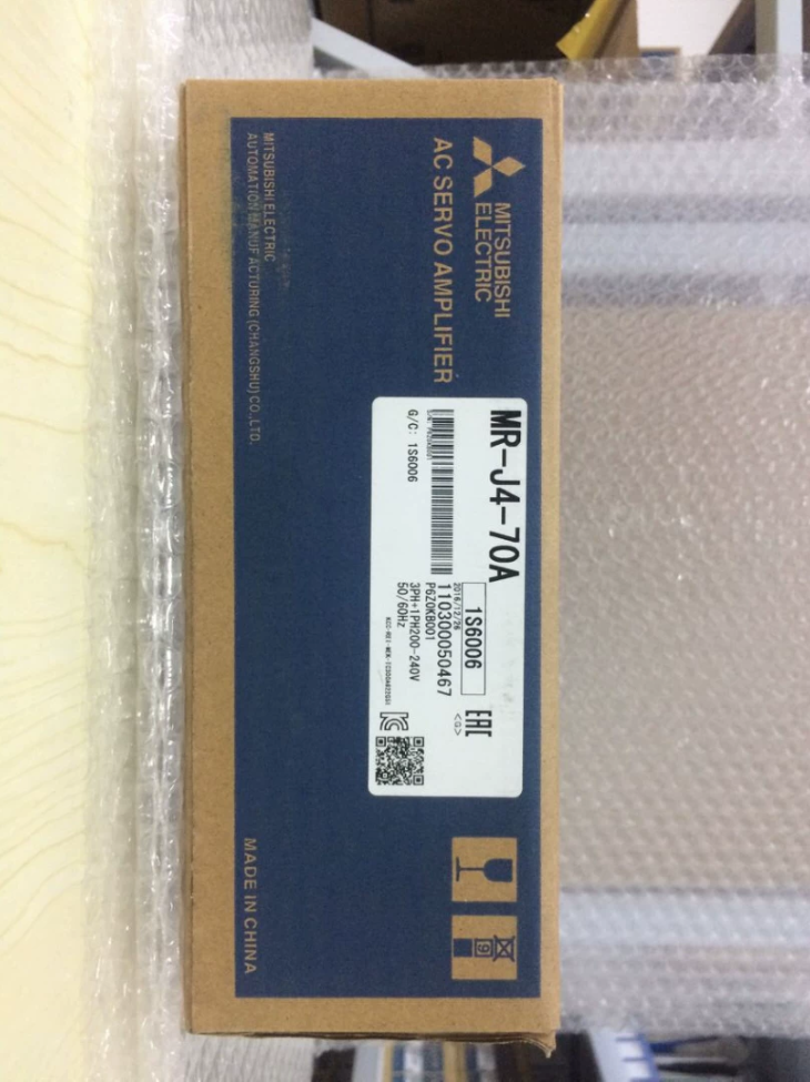

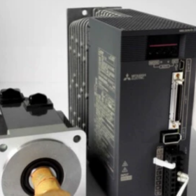
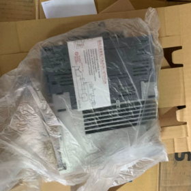
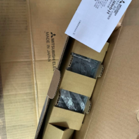
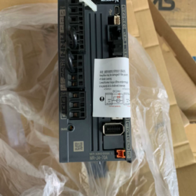
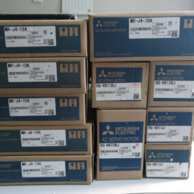
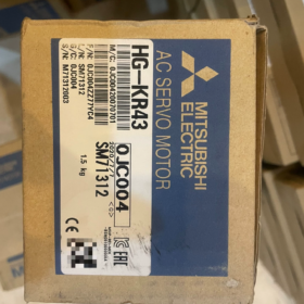
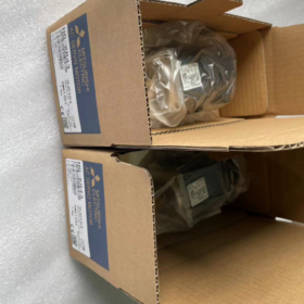
(MELSERVO-J4 Series, 3.5 kW)
MR-J4: 4th-generation high-performance servo amplifier of J4 series
350: Rated power 3.5 kW
A: Pulse + analog general-purpose interface (hard-wired command, no SSCNET optical fibre bus). Bus version: MR-J4-350B. Suffix -RJ: Supports external linear encoder for full closed-loop control.
⚠️ Models of 3.5 kW and higher only accept 3-phase AC200-240V main power supply. Single-phase supply is NOT allowed.
Core Electrical Specifications
| Item | Parameter |
| Main circuit input | 3‑phase AC200‑240V, 50/60Hz; permissible range:170‑264V |
| Rated input current | 21.7A |
| Rated output current | 20A |
| Peak output current | 60A (3‑fold, max.10s short‑time) |
| Control power supply | DC24V±10%, 0.5A (including STO safety circuit) |
| Speed loop bandwidth | 2.5 kHz |
| Built‑in regenerative resistor | 850W; external regenerative resistor required for vertical loads or frequent start‑stop cycles |
| Safety function | STO (Safe Torque Off), compliant with IEC61800‑5‑2 |
| Pulse command | Differential:4Mpps; Open‑collector:200kpps |
| Analog command | ±10V (speed / torque reference) |
| Encoder resolution | Matched motor: 22‑bit (4194304 p/r) |
| Overall dimensions | 140×180×195 mm |
| Weight | 2.8 kg |
| Protection class | IP20, for cabinet installation only |
Compatible Servo Motors (200V Class)
Medium inertia: HG-SR352, HG-SR353; With brake: HG-SR352B, HG-SR353B
Low inertia: HG-KR353, HG-KR353B (with brake)
J2S / JE series motors cannot be used directly due to encoder protocol incompatibility.
Interface Overview
- CN1: I/O signal terminal block, pulse/direction, ±10V analog input, digital DI/DO, STO safety circuit
- CN2: Motor encoder connector
- CN3: USB service port, for PC connection with MR-Configurator2 for commissioning, monitoring and parameter backup
- CN4: Full-closed-loop linear encoder interface (activated for -RJ variant only)
- Main circuit terminals: L1/L2/L3 main power; U/V/W to motor; B1-B2 for external regenerative resistor.
Main Features
Three switchable control modes: Position, Speed, Torque. Compatible with pulse-output PLC (FX/Q/L/R series) and 3rd-party pulse motion controllers.
Advanced Vibration Suppression Ⅱ, adaptive filter, auto-tuning, ToughDrive instantaneous power failure protection, quadrant protrusion compensation, machine diagnosis function.
A/B/Z phase encoder pulse output, 2-channel analog monitor output.
Drop-in replacement for MR-J3-350A (mechanical mounting compatible; parameters require re-tuning).
Alternative Selection Reference
- Same series bus version: MR-J4-350B (SSCNET Ⅲ/H optical fibre bus, for multi-axis synchronous systems)
- New-generation upgrade: MR-J5-350A (higher bandwidth; hardware mounting not fully compatible, wiring and motor compatibility to be verified).
- Retrofit for legacy equipment: Upgrade MR-J3-350A to this unit; pay attention to regenerative resistor and parameter migration.
Second-hand Unit Inspection Checklist
- Visual check: Burnt marks, scorched terminals, bulging capacitors.
- Insulation test: Megger test between main-circuit U/V/W and protective earth.
- Power-on without motor: Check for alarms; verify STO circuit status.
- No-load motor jog test: Check abnormal noise, vibration and encoder feedback.
- Use MR-Configurator2 to read internal alarm history.
Common Alarms
AL.30: Regenerative error. Check regenerative resistor sizing. External resistor is mandatory for frequent start-stop or vertical axis applications.
AL.16: Encoder communication error. Inspect CN2 cable and connectors.
AL.E6: STO circuit open. CN1 STO terminals not short-circuited or external safety signal triggered.
Supplementary Notes for MR-J4-350A (Section 2)
- Typical Pulse-Direction Wiring for Position Control
CN1 terminals, differential signalling (recommended for high noise immunity, for PLC differential output)
- Pulse command: PP ← PLC pulse output; NP ← pulse negative
- Direction command: PD ← PLC direction output; ND ← direction negative
- STO safety circuit: Short-circuit STO1-STO2 and STO3-STO4 on CN1, otherwise AL.E6 occurs and servo cannot run.
- DC24V control supply: DICOM to 24V+; DOCOM to 24V-.
Parameter Settings for Pulse-Direction Mode
| Parameter No. | Setting | Description |
| Pr.000 | 0 | Position control mode |
| Pr.001 | 1 | Pulse + direction input mode |
| Pr.042 | 10000 | Electronic gear numerator, adjust as‑required |
Open-collector Mode (Legacy PLC, not recommended for long cable runs)
Max. pulse frequency limited to 200 kpps; cable length ≤3 m, susceptible to electromagnetic interference.
Wiring Precautions
- L1/L2/L3 must be fed with 3-phase 200-240V AC. Never apply single-phase 220V to MR-J4-350A, power-supply fault alarm will trigger.
- Incorrect U/V-W phase sequence causes shaking and AL.37 alarm.
- Use Mitsubishi shielded servo cable for CN2 encoder wiring; shield grounding at both ends.
Commissioning Software
MR-Configurator2. Connect PC USB to CN3 for jog operation, auto-tuning, alarm history reading and parameter backup.
Full Differences & Replacement Guide: MR-J4-350A replacing MR-J3-350A
Original unit: MR-J3-350A; Replacement unit: MR-J4-350A; Both 3.5 kW, 200V class.
- Mechanical Installation & Hardware
- Mounting cut-out fully compatible: Screw hole positions match, direct retrofit without cabinet modification.
- Overall dimensions nearly identical; heat-sink layout differs without impact on fitting.
- Main-circuit terminals L1/L2/L3, U/V/W, B1-B2 for regenerative resistor: pin-to-pin identical. Existing power cables and external regenerative resistor can be reused.
- ✅Major difference: CN1 control I/O connector
MR-J3-350A: Spring-clamp terminal block
MR-J4-350A: Removable plug-in connector
Field retrofit note: Existing MR-J3 CN1 harness cannot plug directly into MR-J4. Two options:
① Purchase dedicated CN1 plug for MR-J4 and re-terminate existing wires.
② Keep old J3 terminal block and implement external flying-wire adapter.
- CN2 encoder connector: Same physical plug, different protocol
MR-J4-350A can drive legacy MR-J3 HF-SP352 motor (firmware version A8 or above).
MR-J3 cannot drive J4-series HG-SR motors.
Physical encoder cable plug fits, double-check for vertical axes; use genuine shielded cables.
- New CN3 USB service port (absent on MR-J3). Use MR-Configurator2 for setup.
- STO safety circuit (Root cause for AL.E6)
MR-J3 has no built-in STO safety function.
MR-J4 STO terminals are open by factory default. Short-circuit STO1-STO2 and STO3-STO4 on CN1, otherwise AL.E6 appears immediately after power-on. This is the most frequent field pitfall during replacement.
- Regenerative Resistor Comparison
| Item | MR‑J3‑350A | MR‑J4‑350A |
| Permitted power of built‑in regenerative resistor | 300W | 850W |
| B1‑B2 terminal definition | Identical | Identical |
Existing external regenerative resistor can remain in-service. For frequent start-stop or vertical-axis loads, do not rely solely on internal resistor; keep external resistor connected.
- Motor Compatibility
- ✅MR-J4-350A supports legacy HF-SP352 / HF-SP352B motors from J3 platform, firmware ≥A8 required.
- ❌MR-J3-350A cannot drive J4-series HG-SR352 motors.
- Motor power cables: mechanically interchangeable for reuse. Encoder cables share identical plug but differ in protocol; legacy HF-motor cables are acceptable.
- Parameter Migration (Do NOT import MR-J3 parameter files directly)
MR-J3 parameter files cannot be loaded into MR-J4. Partial parameter numbers have changed; enter values manually, do not copy all parameters wholesale.
Key Parameter Mapping (Pulse-Direction Position Mode)
| Function | MR‑J3 Parameter No. | MR‑J4 Parameter No. | Remarks |
| Control mode selection | Pr.0 | Pr.000 | Position mode =0 |
| Pulse input mode (Pulse+Direction) | Pr.1 | Pr.001 | Pulse+Direction =1 |
| Electronic gear numerator | Pr.42 | Pr.042 | Electronic gear ratio must be re‑verified |
| Electronic gear denominator | Pr.43 | Pr.043 | |
| Max. command pulse frequency | Pr.21 | Pr.021 | MR‑J4 differential input up to 4Mpps vs. MR‑J3 max.1Mpps |
MR-J4 accepts higher pulse frequency (4Mpps differential, MR-J3 only 1Mpps). Higher pulse rates from PLC are achievable after replacement.
Tuning Remarks
MR-J4 implements Advanced Vibration Suppression Ⅱ and adaptive filter gains. Do not copy gain values directly from MR-J3. Run auto-tune after replacement and fine-tune gains.
- Step-by-Step Power-on Retrofit Procedure
- Power off equipment; remove MR-J3-350A and mount MR-J4-350A in-situ.
- Retain existing wiring for main-circuit L1/L2/L3, U/V/W and B1-B2 regenerative resistor.
- Process CN1: Fit dedicated MR-J4 plug; short-circuit STO1-STO2 and STO3-STO4 to prevent AL.E6.
- Connect CN2 encoder cable. For legacy HF-SP motors, confirm drive firmware ≥A8.
- Power-on; perform factory reset first, then manually input critical parameters (mode, pulse-input format, electronic gear ratio).
- No-load jog test to verify rotation direction. Reverse direction by modifying bit setting inside Pr.000 (software reversal), do not swap U/V/W power phases.
- Execute auto-tune. Run machine under load; monitor for vibration or noise. Watch regenerative load factor to avoid AL.30 regenerative error.
- Typical Replacement-related Faults
- AL.E6: STO circuit not short-circuited. MR-J3 lacks STO, this fault is highly common in retrofits.
- AL.16 Encoder error: Legacy J3 motor used with outdated drive firmware → upgrade firmware.
- Poor positioning accuracy / vibration: Do not reuse J3 gain settings; perform new auto-tuning.
- AL.30 Regenerative error: Frequent start-stop / vertical axis → inspect external regenerative resistor.
- No response to pulse command: Double-check Pr.001 pulse-input-mode setting.
- PLC Program Considerations
Power-up initialization duration differs between MR-J3 and MR-J4. For vertical-axis machines, add a short delay in PLC logic after servo-ready signal to prevent axis dropping.





NH42-63-318x560.png "CHINT PC-type automatic transfer switches (ATS)NH42-63/4SZ")



