 Contactor,circuit breaker,sensor,Encoder,PLC,Converter

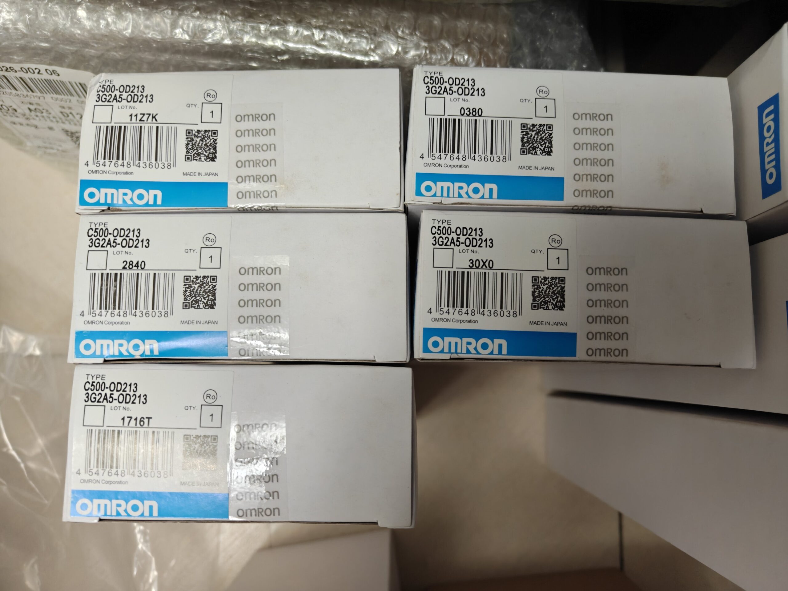












OMRON C500-OD213 (3G2A5-OD213) Replacement Model Summary
Critical Premise: No drop-in replacement module fits the original C500 rack. The C500 backplane bus is obsolete. Three upgrade approaches: spare-part maintenance, full-PLC upgrade, remote I/O retrofit.
Key specifications of original unit: 64-point NPN sinking transistor output, DC12-24 V, 0.1 A per point, 8 points per COM group, dual 40-pin MIL connectors.
Option A: Retain original C500 system (spare-part swap only, no rack/program modification)
(Alternative part number: 3G2A5-OD213)
Series: SYSMAC C500 rack-mount PLC, fully obsolete; manufacturer support terminated (end-of-support March 2015). Only used / surplus spare parts are available on the market.
Module Type: 64-point transistor output unit (NPN sinking type), MIL-C connector interface, no screw terminal block.
Model Code Decoding
| Field | Description |
| C500 | SYSMAC‑C500 rack‑mount PLC series |
| OD | Output‑DC Transistor |
| 213 | Module version / specification code; legacy part number 3G2A5‑OD213 |
Core Electrical Specifications
| Item | Specifications |
| Output Points | 64 points, 8 points per common terminal (8 COM groups total) |
| Output Type | NPN sinking transistor output |
| Load Voltage | DC 12‑24 V |
| Rated current per point | 0.1 A (100 mA); max. 0.8 A per COM group; total max. 6.4 A for module |
| Output Response | ON ≤0.2 ms; OFF ≤0.3 ms |
| Isolation | Photocoupler isolation |
| External Power Supply | DC5‑24V, ≥170 mA (for output circuit) |
| Power Consumption | Powered via backplane bus |
| Interface | 2 × 40‑pin MIL flat‑cable connectors (no screw terminals) |
| Environmental Conditions | Operating temperature: 0~55℃; storage temperature:‑20~70℃; humidity 35‑85%RH, condensation not permitted |
| Weight | Approx. 0.6 kg |
Operating Principle & Signal Flow
- Logic output signals from the CPU backplane bus are fed to the module internal logic circuit.
- Signals drive NPN transistors through photocoupler isolation.
- When transistor turns ON: load negative terminal is pulled to GND; load positive terminal connects to external DC24V.
- Every 8 output points share one COM pin; COM must connect to external power-supply GND.
⚠️ The module does NOT supply output-side power; all load power must be provided externally.
Installation & Wiring Guidelines
- Install only in I/O slots of C500 CPU rack or expansion rack; hot-plug via backplane bus.
- Output signals use 40-pin MIL flat cables. Direct bare-wire connection is not allowed. A matching conversion terminal board is required.
- The COM terminal for each 8-point group must be reliably connected to external DC24V-GND. Different COM groups can be grounded separately or share a common ground.
- It is recommended to fit an external fuse (≤0.125 A) for each channel. No point-level self-recovery fuses are built-in.
- For inductive loads (relays, solenoid valves), fit free-wheeling diodes with reverse voltage ≥35 V.
Hard-Restriction Rules (Forbidden Operations)
❌ Never apply AC voltage to output channels; this will burn out the module immediately.
❌ Per-channel current must never exceed 100 mA; per-COM-group current must never exceed 0.8 A.
❌ Do not sharply bend MIL flat cables; do not disconnect connectors under power.
❌ Do not operate under condensing or corrosive-gas conditions.
Troubleshooting
| Symptom | Root Cause | Remedy |
| Program shows output ON but no response at channel | 1. Missing load power; 2. COM terminal not connected to GND; 3. Transistor breakdown; 4. Broken wiring | Measure COM potential; check free‑wheeling diodes; use spare channel or replace module |
| Entire 8‑point group has no output | Open‑circuit / missing ground on corresponding COM circuit | Inspect COM pin wiring and conversion terminal board |
| Spurious output / false triggering | External interference; missing free‑wheeling diodes; excessive power‑supply ripple | Apply shielding; add diodes for inductive loads; filter DC24V power supply |
| All module indicators off | Poor backplane‑bus contact; rack power‑supply failure | Power off, re‑seat module; inspect rack power unit |
Replacement Options
Important: No new module can plug-and-play into the legacy C500 rack. The C500 backplane hardware is obsolete. Two upgrade strategies are available.
Option 1: Maintain existing C500 system (spare-part-only repair)
Only option: used / salvaged C500-OD213 (3G2A5-OD213). All 64 channels must be tested upon receipt.
Risks: component aging, no OEM warranty.
Option 2: System upgrade (Recommended)
- CS1-series upgrade: CS1G-CPU + CS1W-OD261 (64-point transistor, MIL connector). C500 rack cannot be reused; new backplane rack required.
- CJ1/CJ2 compact-rack: CJ1W-OD261 (64-point output). Smaller footprint. Requires full replacement of CPU, power supply and rack; program porting is mandatory.
Note: CJ1W-OD213 is an 8-point output module. It is NOT a replacement for C500-OD213. The two are completely incompatible. Do not confuse part numbers.
Typical Application Scenarios
Legacy equipment: imported production lines from the 1990s, packaging machinery, textile machinery, older assembly lines. C500 racks plus OD213 modules are widely deployed to drive 64-channel solenoid valves and miniature relays.
Selection Pitfall Avoidance
- Distinguish part numbers: C500-ID213 is input module; OD213 is output module. They cannot be interchanged.
- This unit uses MIL-style connectors instead of screw terminals. When ordering spares, confirm availability of matching conversion terminal boards and flat cables.
- Per-channel maximum current is only 100 mA. Not for direct drive of high-current loads; use intermediate relays.
Sole solution: used / salvaged C500-OD213 (3G2A5-OD213)
Risks: component ageing, no OEM warranty. Test all 64 output channels on arrival.
❗ Warning: CJ1W-OD213 cannot be used as replacement. It is only 8-point. Similar-sounding model number, incompatible backplane and rack; frequent procurement mistake.
Option B: Full upgrade to modern OMRON PLC (new genuine components, recommended)
Full replacement of CPU, power supply and rack; PLC program porting required. I/O electrical characteristics match: 64-point NPN sinking, MIL-40 connectors.
| Replacement Model | Series | Points | Output Type | Remarks |
| CS1W‑OD261 | CS1 | 64 | NPN sinking transistor | Closest electrical match for legacy‑machine retrofits. Requires CS1 CPU + CS1 rack. C500 rack cannot be reused |
| CJ1W‑OD262 | CJ1 | 64 | NPN sinking transistor | Compact size, cost‑effective. Requires CJ1 CPU + CJ‑series rack |
| CJ2W‑OD262 | CJ2 | 64 | NPN sinking transistor | Latest‑generation CJ2 platform, enhanced performance |
Parameter difference: original C500-OD213 uses 8 points per COM. CS1W-OD261 / CJ1W-OD262 adopt 16 points per COM. Field-wiring grouping for DC24V-GND must be redesigned. Per-point drive capability remains unchanged despite higher group current rating.
Option C: Remote I/O retrofit (keep original C500-CPU; remove local OD213)
Retain C500-CPU; replace local 64-point output with communication-based remote I/O. CPU and most user program can be preserved, but field wiring must be modified:
- Fit C500-RM201 remote master module plus remote slave unit:
SRT2-OD261: 64-point NPN transistor remote output unit with MIL connector.
Pros: CPU unchanged, minimal program adjustment. Cons: additional master hardware and remote cabling; introduces communication-link failure risk.
Option D: Domestic third-party solution (cost-oriented full-system retrofit)
No third-party module can plug into C500 rack. Complete PLC replacement is mandatory:
Domestic PLC (Inovance H3U/H5U, Xinje XD/XG etc.) + 64-point NPN sinking output module, plus MIL-40 conversion terminal board.
Entire PLC program must be rewritten. Suitable for overhaul projects with tight budget constraints.
Procurement & Retrofit Pitfall Checklist
- Strictly distinguish C500-OD213 (64-point) vs CJ1W-OD213 (8-point): similar nomenclature yet fully incompatible, a common purchasing error.
- CS1W-OD261 / CJ1W-OD262 use 16-point COM groups versus the original 8-point groups. Re-plan external DC24V-GND wiring during retrofit.
- Connectors: legacy MIL-C flat cables can be reused, but terminal-board pin-out must be cross-checked against manuals. Never power-up directly without verification.
- Fit free-wheeling diodes for inductive loads; keep per-point current below 100 mA.
Upgrade-path Recommendation
- Short-downtime urgent production recovery: install used original C500-OD213 for immediate restoration; schedule full system upgrade during future planned shutdowns.
- Acceptable downtime for program modification: prefer CS1W-OD261 (CS1-system), best electrical compatibility with legacy equipment.
- Target service-life extension of 3-5+ years: select CJ2-series CJ2W-OD262.
OMRON C500-OD213 (3G2A5-OD213) Application Scope
Module profile: 64-point NPN sinking transistor output unit, part of the 1990s-era SYSMAC-C500 large-scale PLC platform. Designed for high-density low-current drive of solenoid valves, miniature relays and indicator lamps. Only found on ageing installed-base machinery; not for new projects.
Compatible Load Profile
Rated max. 100 mA per point for DC12-24 V loads: solenoid coils, miniature DC relays, signal lamps.
Not for direct drive of high-power contactors or heaters; intermediate relays are required for heavy-duty loads.
Dual 40-pin MIL connectors deployed with flat cables and conversion terminal boards for high-density signal wiring.
Main Industries & Equipment Use-Cases
1️⃣ Packaging Machinery
Vertical / horizontal packaging machines, bag-making machines, filling and carton-sealing equipment
Function: bulk control of pneumatic solenoid-valve banks for cylinder actuation, feeding, cutting, pressing and material baffles. High-channel-count cylinder systems use this 64-point module to reduce rack-slot consumption.
2️⃣ Textile Machinery (mostly legacy imported units)
Air-jet looms, water-jet looms, carding machines, legacy dyeing & finishing production lines
Function: drive large numbers of pneumatic directional valves, weft-selection solenoids, indicator lamps and logic relays. Multi-piece OD213 configurations deliver massive I/O capacity for textile plants.
3️⃣ Early-generation Automotive-Component Assembly Lines
Legacy assembly lines, tooling fixtures, test stations, conveyor systems
Function: control pneumatic clamping fixtures, stop cylinders, status lamps and sorting actuators. Centralised solenoid-valve drive for multi-station production cells.
4️⃣ Legacy Material-Handling & Sorting Equipment
Older roller conveyors, sorters, transfer and lifting mechanisms
Function: actuate diverting baffles, sorting cylinders, change-over mechanisms and position-indicator lamps. Suited for high-density discrete-output conveyor applications.
5️⃣ Plastics & Rubber Machinery (imported legacy equipment)
Large injection-moulding auxiliary equipment, robotic part-removal units, rubber-vulcanisation lines
Function: drive mould core-pull solenoids, ejector actuators, material-path switch valves and alarm lamps.
6️⃣ Light-Industry Metallurgy & Building-Material Lines
Building-material production lines, auxiliary metallurgy equipment, ceramic-processing lines
Function: control pneumatic actuators, material baffles, sorting mechanisms and status indication. Frequently fitted on imported complete-plant systems of that era.
7️⃣ General-purpose imported turn-key production lines (1990-early-2000s)
Many European and Japanese turn-key plants adopted the C500 platform with C500-OD213 for high-density output. This explains strong aftermarket spare-part demand today.
Non-applicable Scenarios (hard-selection limits for this module)
- ❌ AC loads: DC-transistor output hardware; direct connection to AC solenoid valves will destroy the unit.
- ❌ Loads exceeding 100 mA per channel or high-power contactors: intermediate relays mandatory.
- ❌ High-vibration, condensing or corrosive-gas environments.
- ❌ New-build projects: full C500 platform is obsolete and must not be specified.
Operational-Maintenance Profile
Today C500-OD213 units are almost exclusively encountered in spare-part-repair scenarios: the host machine remains in service while the module has failed. Users must source used spares or execute system-modernisation projects.
| AK1782HB 17689/AC220V/240V0.23A 175×175х90″ |
| PFB1224UHEC8 120х120х30 |
| FFR0624SHE 24 В 0,40 А 80X80X30″ |
| capacitor” CBB65 35 мкф на 450в”, |
| capacitor”CBB65 450В 50 мкф”,10 |
| capacitor”CBB65 45 мкф на 450в”, |
| capacitor”CBB61, 4мкф, 450В, 5%” |
| capacitor”CBB61, 3мкф, 450В, 5%” |
| capacitor”CBB61, 2,5мкф, 450В, 5%” |
| VNY 4 NS/NT art 481046″ |
| Temperature/indicator block”GEFRAN 40T-48-4-00-RR-0-0-0-0″ |
| X20DI9371 Rev.GO” |
| X20 BM11″ |
| Omron DRT1-AD04 24 VDC” |
| DRT2-OD16ML Разъем DRT 2NPN 24 B” |
| C200HW-PA204 100-240 В |
| C200HG-CPU43-E |
| CJ1W-DRM21 Omron |
| Omron C200HW-CLK21″ |
| C200H-OD219 OMRON” |
| C200H DA004 |
| C500-OD218 3G2A5-OD218″ |
| C200H-ID217SYSMAC C200H” |
| DCN1 3″ |
| CVM1-PA208″, |
| CVM1-CLK21″,1 |
| CV500-ETN01″ |
| CVM1-CPU11-V2″ |
| “C500-OD213 3G2A5-OD213” |
| C500-AD501″ |
| BH24047 315 В 230 В” |
| BH16097/230V 300W |
| 3IF060.6 REV D0″ |
| SLC 500 1747-BA Ser-A”, |
| S15-PA-5-C11-PK” |
| BHT 16.24A 1000/403622″ |
| BHT 16.21A 1500/403622″ |
| BHT 16.24A 5000/403622″ |
| BTK-2-111-DIN” |
| 603C01″ |
| Sensor KEYENCE LR-TB5000 |
| IFM/IFM IE5099 IEC3002-BPOG |
| IF5330 IFA3004-BPKG |
| IF5333 IFA3004-APKG |
| UNDK 20P11/099186 PNP |
| IFM 203 10-36V |
| sbfx1 12-24vac |





NH42-63-318x560.png "CHINT PC-type automatic transfer switches (ATS)NH42-63/4SZ")



