 Contactor,circuit breaker,sensor,Encoder,PLC,Converter


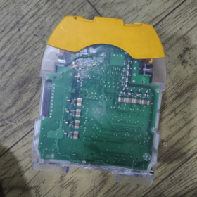
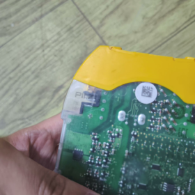
Basic Model Information
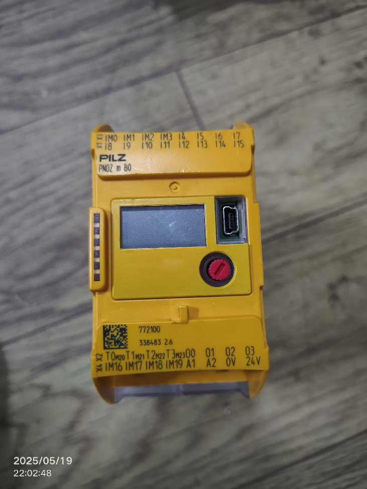
Part No.: 772100
Product Name: PNOZ X2 24VAC Safety Relay
Brand: PILZ (German safety automation brand)
- Core Electrical Specifications
- Supply Voltage: 24 V AC
- Safety Contacts: 2 normally open (NO) safety output contacts
- Auxiliary Contacts: None
- Safety Classification
EN ISO 13849-1: Cat. 4 / PL e
IEC 61508: SIL 3
- Input Circuit: Single-channel E-stop / safety gate input with spring terminal wiring
- Contact Ratings
Resistive Load: 230V / 6A
Minimum Switching Current: 1mA / 5V DC
- Functional Description
Standard basic safety relay compatible with E-stop buttons, safety gate switches and safety mats
Auto-reset mode (no reset button; outputs close automatically after power recovery)
Compact module for DIN rail mounting (35mm standard rail)
Housing width: 22.5mm
- Environmental & Mechanical Parameters
Operating Temperature: 0 ~ +55 ℃
Storage Temperature: -20 ~ +70 ℃
Protection Class: IP20 (for cabinet installation only)
Certifications: CE, UL, CSA
- Typical Replacement Models
- Equivalent DC version: 772101 (PNOZ X2 24VDC)
- Manual reset version: 772130 (PNOZ X2.1 24VAC)
- Wider multi-contact version: PNOZ X3 / X4 series
PILZ 772100 (PNOZ X2 24VAC) Complete Terminal, Wiring, Dimension & Troubleshooting Manual
- Basic Model Information
Order No.: 772100
Model: PNOZ X2 24VAC
Supply: 24V AC
Reset Mode: Auto-reset (no external start terminals; outputs close upon power restoration)
Safety Contacts: 2 force-guided normally open contacts 13-14 / 23-24
Safety Level: Cat.4 / PL e / SIL3
- Complete Terminal Definition (Top to Bottom)
2.1 Power Terminals (Left Supply Area)
A1: 24V AC Live (L)
A2: 24V AC Neutral (N)
> Supply range: 20.4~26.4V AC; a 1A slow-blow fuse is recommended upstream
2.2 Safety Input Monitoring Terminals (Middle Input Circuit)
S11: Common input terminal (24V AC incoming line)
S12: Channel 1 input (one end of E-stop/safety gate NC contact)
S22: Channel 2 input (second redundant channel for dual-circuit design)
> This model has no S21 and no Y1/Y2 start terminals, purely auto-reset design
2.3 Safety Output Contacts (Right Load Circuit)
- 13-14: 1st set of force-guided safety NO contacts
- 23-24: 2nd set of force-guided safety NO contacts
No auxiliary contacts or feedback circuit terminals
- Two Standard Wiring Schemes (Field Commonly Used)
Scheme 1: Single-channel Wiring (Only meets PL d, for simple low-risk machines)
Application: Low-risk equipment with single E-stop only
- Connect S11 to 24V AC L
- Short-circuit S12 and S22 together
- Wire E-stop NC contacts in series to the short joint, then route back to A2 (N)
Principle: Two input lines shorted; internal single-channel monitoring only, unable to detect short circuits between contacts
Scheme 2: Dual-channel Redundant Wiring (Mandatory Cat.4/PL e for Machine Tools & Automation Lines)
Application: Injection molding, stamping, robotics, production line safety gates
- S11 = 24V AC L
- S12: 1st NC contact of E-stop
- S22: 2nd NC contact of E-stop
- Parallel the other ends of both contacts and connect to A2 (N)
Advantages: Detects input earth short circuits, inter-cable short circuits and single contact welding
Standard Output Wiring
Wire contactor coils and main circuit control power in series with 13-14 + 23-24 in series (dual safety cut-off)
Resistive load: 230V/6A
Inductive contactor load: Install RC surge suppressor in parallel with coil
Fit a 6A fuse upstream of outputs to prevent contact welding
- Mounting Dimensions & Wiring Specifications
Overall Mechanical Dimensions (mm)
Width × Height × Depth: 22.5 × 87 × 121
Mounting: Snap-on installation on 35mm standard DIN rail
Weight: Approx. 190g
Protection: IP20, cabinet use only
Terminal Wiring Requirements
Screw terminal torque: 0.6 N·m
Wire stripping length: 7mm
Cable cross-section: Solid wire 0.2~4mm²; stranded wire with ferrule 0.2~2.5mm²
Max total length of input circuit cables: ≤300m (line resistance ≤30Ω limit for AC models)
- Front Panel Indicator Meanings
- Green POWER LED: Power supply normal
- Green CH1 / CH2 LEDs: Corresponding input channel circuit closed (safe state)
Indicator Status Reference Table
| Phenomenon | Equipment Status |
| POWER LED off | No 24VAC supply, blown fuse, reversed/short-circuited A1/A2 terminals |
| POWER LED on, CH1/CH2 all off | E-stop activated, safety gate open, broken input cable or input earth short |
| POWER LED on, single CH LED off | Open circuit in one dual channel, damaged contact, locked fault due to inter-cable short |
| All LEDs on, no voltage at outputs | Internal contact welding, irreversible module hardware failure |
- Troubleshooting Matrix (Phenomenon → Root Cause → Resolution Steps)
Fault 1: POWER LED fails to light up after power-on
- No 24VAC measured at A1-A2: Check upstream circuit breaker, fuse and transformer supply
- Normal voltage at A1/A2 but LED remains off: Internal power supply damaged; replace 772100 directly
- Terminal short circuit: Cut power, rework wiring and eliminate cable insulation earth leakage
Fault 2: Power supply normal, CH LEDs off, safety outputs de-energized
- E-stop NC contact open: Reset E-stop button
- Broken input cable: Measure continuity between S11-S12/S22 section by section
- Input cable earth short: Disconnect cables and locate grounding fault segment by segment
- Single contact failure under dual-channel wiring: Replace dual-circuit E-stop switch
Fault 3: All LEDs illuminated but machine fails to start (no output at 13-14/23-24)
- Blown output circuit fuse: Replace fuse and check for shorted contactor coil
- Welded safety contacts: Irreparable module damage; install new unit
- Load current exceeding 6A: Add intermediate relay to expand output capacity
Fault 4: Random tripping and CH LED extinction during operation (intermittent fault)
- Excessively long cables with excessive line resistance: Use thicker cables or shorten wiring routes
- Interference from power cables routed alongside safety wiring: Separate cable runs with ≥20cm clearance
- High contact resistance caused by oxidized contacts: Replace E-stop / safety gate switch
- Strict Forbidden Operations (Violation leads to lost safety certification or burnt module)
- Never connect 220V mains to A1/A2; only 24V AC is permitted
- Never omit the second contact in dual-channel wiring (Cat.4 compliance cannot be achieved)
- Never feed an independent external power source to input circuits; input power must share the same 24VAC supply as module A1/A2
- Do not parallel output contacts for capacity expansion; series connection only. Use external safety contactors for load expansion
- Never drive high-power inductive loads without fuses; high risk of contact welding
- Do not plug/unplug input cables while the module is live; electric arcs will damage internal monitoring circuitry
- Equivalent Series Replacement Reference
- DC alternative: 772101 (PNOZ X2 24VDC, identical terminal layout, 24V DC supply only)
- Manual reset model: 772130 (PNOZ X2.1 24VAC, added Y1/Y2 start terminals requiring external reset button)
- Multi-contact upgrade: 774300 PNOZ X3 (3 safety contacts, 45mm width)
- Complete Part Number List for PILZ PNOZ X2 Series (22.5mm width, 2 NO safety contacts, Cat.4/PL e/SIL3)
Benchmark Reference: 772100 = PNOZ X2 24VAC auto-reset, no manual start terminals
1.1 Pure Auto-reset Models (No Y1/Y2 reset terminals, direct equivalent to 772100)
| Part No. | Full Model Name | Supply Voltage | Terminal Type | Reset Mode |
| 772100 | PNOZ X2 24VAC | 24V AC | Fixed screw terminals | Auto-reset |
| 772101 | PNOZ X2 24VDC | 24V DC | Fixed screw terminals | Auto-reset |
| 774053 | PNOZ X7 110VAC | 110V AC | Fixed screw terminals | Auto/Manual dual compatible |
| 774055 | PNOZ X7 120VAC | 120V AC | Fixed screw terminals | Auto/Manual dual compatible |
| 774057 | PNOZ X7 240VAC | 240V AC | Fixed screw terminals | Auto/Manual dual compatible |
1.2 Manual Controlled Reset Models (X2.1 series with external Y1/Y2 reset button)
| Part No. | Full Model Name | Supply Voltage | Terminals | Features |
| 772130 | PNOZ X2.1 24VAC | 24V AC | Screw terminals | External reset, dual-channel short-circuit detection |
| 772131 | PNOZ X2.1 24VDC | 24V DC | Screw terminals | External reset |
| 777300 | PNOZ X2P 24VACDC | Universal 24V AC/DC | Plug-in spring terminals | Auto/Manual dual mode |
1.3 45mm Wide X2C Series with Feedback Circuits (Controlled start, equipment feedback monitoring)
777303 PNOZ X2P C 24VACDC: Spring terminals with equipment feedback monitoring
774303 PNOZ X2 24VACDC: Universal AC/DC base model
1.4 Distinction Notes (Avoid Selection Mistakes)
- 772100 ≠ PNOZ m B0: PNOZ m B0 (marked 772100) is a modular safety controller, completely different product category from PNOZ X2 safety relay. Same part number but unrelated products. All replacements below apply exclusively to PNOZ X2 24VAC safety relay 772100.
- Model 772100 X2 only: 22.5mm width, 2 NO safety contacts, no auxiliary contacts, pure auto-reset.
- Cross-brand Equivalent Replacement Table (Matching 772100: 24VAC, dual-channel, 2 safety NO contacts, auto-reset, Cat.4 PL e SIL3)
2.1 Schneider Preventa XPS Series
| Application Scenario | Replacement Model | Matching Rate | Difference Description |
| Direct drop-in replacement for 772100 (24VAC auto-reset) | XPS-AC3110 | 95% | 2 safety NO contacts, dual-channel E-stop/safety gate monitoring, auto-reset; 22.5mm width, 24VAC supply |
| Universal AC/DC version | XPS-AC5110 | 90% | 24VAC/DC universal, identical functions, minor difference in terminal layout |
| Alternative manual reset model | XPS-AC3710 | 85% | Requires external reset button, suitable for machines requiring startup confirmation |
2.2 ABB Safety Safety Relays
| Replacement Model | Matching Rate | Key Specifications |
| C571.04 24VAC | 93% | 2 safety NO contacts, dual-channel monitoring, auto-reset, Cat.4 PL e, 22.5mm DIN width |
| C571.05 24UC | 90% | Universal AC/DC, all other functions identical |
2.3 OMRON G9SE Series (Most Widely Used Drop-in Equivalent)
| Model | Supply Voltage | Matching Rate | Description |
| G9SE-201 AC24 | 24V AC | 98% Optimal Equivalent | Dual-channel input, 2 force-guided NO contacts, power-on auto-reset, 22.5mm width, SIL3 PL e Cat.4, highly consistent terminal logic with PILZ X2 |
| G9SE-201 DC24 | 24V DC | 98% | Equivalent to DC model 772101 |
2.4 Phoenix Contact PSR Series
| Model | Matching Rate | Compatibility Notes |
| PSR-SCP-24AC/ESA2/2X1 | 92% | 24VAC, 2 safety contacts, auto-reset, dual-channel short-circuit detection, 22.5mm width |
| PSR-SCP-24UC/ESA2/2X1 | 90% | Universal AC/DC with broader compatibility |
2.5 IFM Safety Relays
| Model | Matching Rate | |
| SR0100 24VAC | 90% | Dual-channel E-stop monitoring, 2 safety NO contacts, auto-reset, Cat.4 |
2.6 Domestic Certified Equivalents (Cat.4/PL e/TÜV Certified)
| Brand | Model | Matching Rate | |
| Covestro | SRS2-24AC | 88% | 2 safety NO contacts, dual-channel, auto-reset |
| Euchner | ES202-24AC | 90% | Popular domestic alternative for machine tools |
- Replacement Selection Criteria (Must Verify Before Swap)
3.1 Mandatory Identical Parameters (Otherwise Direct Wiring Impossible)
- Rated supply voltage: 772100 fixed at 24V AC. DC24V models cannot be directly replaced unless an AC/DC power converter is added.
- Reset logic: Original equipment uses auto-reset. Do not select forced manual reset models (X2.1, XPS-AC3710, etc.)
- Number of safety contacts: 2 sets of force-guided NO contacts (13-14 / 23-24). Avoid models with 3NO + 1NC auxiliary contacts.
3.2 Minor Compatible Differences (No Program Modification Required, Minor Wiring Adjustment Only)
- Terminal pitch / terminal type: Screw vs spring terminals only require different crimping tools
- Indicator layout: No impact on safety functions
- Maximum cable length limit: Difference ≤50m among all 22.5mm compact modules, negligible for field wiring
- Modification Precautions for Replacement
- Optimal zero-modification replacement: OMRON G9SE-201 AC24. Near identical terminal definition, dimensions, safety level and auto-reset logic as 772100; electricians can reuse existing wiring without changes.
- Schneider XPS-AC3110 mapping: Input terminals S11/S12/S22 correspond to XPS IN1/COM/IN2; output contact series wiring method is fully identical.
- Mixed model prohibition: Replacing auto-reset unit with manual reset model will prevent automatic machine startup after power-on; external reset button must be installed additionally.
- Safety certification retention: All listed models comply with EN ISO 13849 Cat.4 PL e and IEC 61508 SIL3. Machine overall safety certification remains valid after replacement.
- Load protection: 6A fuse must still be fitted on outputs post replacement; RC snubber circuit mandatory for inductive contactor coils.
- Quick Selection Recommendations
- Imported zero-wiring-modification replacement: G9SE-201 AC24 (OMRON)
- Matching Schneider system equipment: XPS-AC3110
- Phoenix Contact cabinet integrated solution: PSR-SCP-24AC/ESA2/2X1
- Cost-effective domestic alternative: SRS2-24AC (Covestro)
- Replacement for original DC model 772101: G9SE-201 DC24 / XPS-AC5110





NH42-63-318x560.png "CHINT PC-type automatic transfer switches (ATS)NH42-63/4SZ")



