 Contactor,circuit breaker,sensor,Encoder,PLC,Converter

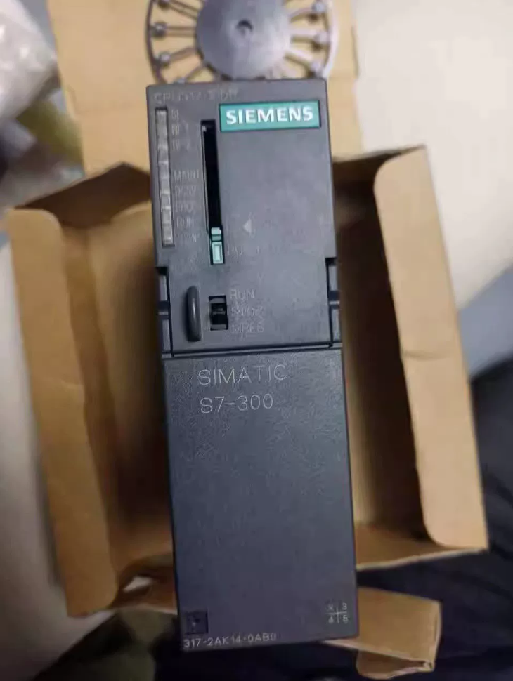

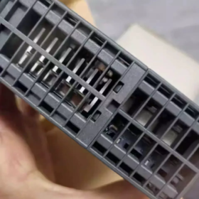
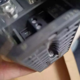
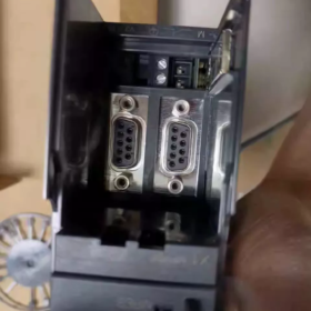
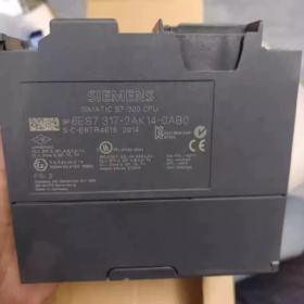
6ES7: SIMATIC S7 automation series
3: S7-300 PLC platform
17: CPU317, high-performance CPU
2: Dual-interface version
A: DP interface variant (no Profinet port, differs from 2EK14 PN/DP model)
K: Hardware revision code
14: Firmware version V2.7
0AB0: Product packaging code, standard German original model
Full designation: CPU317-2DP, S7-300 Central Processing Unit, 1MB work memory, dual DP interfaces, MMC micro memory card mandatory
- Key Technical Specifications
- Memory
Work memory: 1MB (program + data)
Retentive memory: 256KB
Programs, project files and firmware are fully stored on MMC card. CPU cannot start without MMC card.
- Execution Performance
Bit instruction: 25ns; Word instruction: 30ns; Fixed-point instruction: 40ns; Floating-point instruction: 160ns
- Communication Interfaces (2 Independent DP Ports)
Port1: MPI / PROFIBUS-DP, max. 12Mbps, configurable as DP master/slave
Port2: Independent PROFIBUS-DP, master/slave, dual DP bus (this model has no Ethernet Profinet port)
- I/O Capacity
Max. digital I/O: 65536 points (Process Image area: 8192 Bytes)
Max. analog channels: 4096 channels
Max. expansion racks: 3 racks (main rack + 3 expansion racks)
Supports FM function modules and CP communication modules
- Electrical & Mechanical Data
Power supply: DC24V, power consumption approx. 3.5W
Dimensions: 40mm×125mm×130mm, weight approx. 0.406kg
Operating temperature: 0~60℃ (standard S7-300 range)
- Programming Software: STEP7 V5.x, TIA Portal (Classic Mode)
- Product Lifecycle
Officially entered phase-out stage (PM400) from 2023-10-01. New project orders are no longer accepted; spare parts remain available. Circulating units on market are mainly stock items or used/refurbished modules.
Comparison within series:
6ES7317-2AJ10-0AB0: 512KB work memory, older generation; 2AK14 is upgraded version with doubled memory and improved performance. Direct replacement with AJ10 is invalid if program size exceeds 512KB.
6ES7317-2EK14-0AB0: CPU317-2PN/DP with Profinet port, 1MB work memory. Hardware base compatible with AK14, but different communication interfaces, not directly interchangeable.
- Typical Application Scenarios
Main controller for production lines, distributed I/O systems over multi-DP buses
Machine tools, metallurgy, paper, packaging, rubber & plastic and other medium-to-large automation equipment
Multi-drive DP bus control with dual DP network segmentation (one bus for field I/O, one bus for inverters)
PCS7 DCS slave stations, legacy production line retrofit projects
- Model Selection & Replacement Solutions
5.1 Direct replacement on same platform (retrofit of legacy projects, minimal modification)
Same model: 6ES7317-2AK14-0AB0 (spare procurement. Attention required for MMC migration and firmware version matching)
⚠️Note: MMC card cannot be simply unplugged and inserted into new CPU; program and hardware configuration must be re-downloaded. Verify firmware version before replacement to avoid unexpected shutdown.
5.2 Cross-platform upgrade (Recommended for new projects)
S7-300 discontinued, recommended upgrade to S7-1500 series:
CPU1511C-1PN / CPU1513C-1PN; existing DP bus can be retained via ET200SP IM155-6DP interface module for legacy DP slaves.
5.3 Domestic alternative
Domestic PLC (Inovance, Xinje, Co-Trust etc.). Program and DP communication configuration must be completely rewritten. STEP7 project cannot be directly migrated. Suitable for full line renovation.
- Installation & Maintenance Guidelines
- Mandatory MMC requirement: Minimum 4MB, 8MB recommended. PLC fails to run if MMC is damaged or missing. All programs reside on MMC; no onboard storage in CPU.
- Mounting: DIN rail mounting, S7-300 backplane bus. PS307 power supply module is mandatory.
- Earthing: Single-end grounding for DP cable shield to reduce EMC interference. Terminating resistors configured separately for each DP bus.
- Status LEDs: SF (system fault), BF (bus fault), RUN/STOP. For DP bus faults, check terminating resistors, wiring and DP address conflicts first.
- Common Troubleshooting
- SF ON, BF flashing: DP cable breakage, missing terminating resistor, slave station fault, DP address conflict.
- No RUN after power-up, STOP LED steady ON: MMC missing/damaged, firmware corruption, program error.
- Program download failure: Firmware mismatch in STEP7, wrong CPU order number selected in hardware configuration.
- Parameter loss after power cycle: Incorrect retentive area setup, MMC card not fully saved.
- Foreign Trade Information
HS Code: 85371011 (Programmable Logic Controller PLC)
Export Control: ECCN EAR99H, non-military item, normal industrial export.
- Inspection Checklist for Second-hand Units
- Visual check: No burn marks, no oxidation on backplane bus contacts, no water ingress or corrosion.
- Power-on test: Insert functional MMC card; CPU enters RUN mode normally without SF/BF alarms.
- Firmware reading: Read firmware V2.7 online via STEP7, cross-check with label order number.
- Communication test: Test MPI/DP ports separately to verify both DP channels are functional.
- Serial number verification: Read internal serial number to confirm non-relabeled refurbished module.
STEP7 Hardware Configuration Template|6ES7317-2AK14-0AB0 (CPU317-2DP, V2.7)
Applicable software: STEP7 V5.4 / V5.5 / V5.7; TIA Portal Classic Mode can import this hardware configuration
Rack: UR rack (S7-300 rail, Rack 0)
- Rack Slot Allocation (HW Config)
| Slot | Module Name | Order No. | Remarks |
| 1 | PS307 Power Supply | 6ES7307-1EA01-0AA0 (24V 5A) | Replaceable with 1KA01 (2A), select according to load |
| 2 | CPU317-2DP | 6ES7317-2AK14-0AB0, V2.7 | Dual DP ports: X1=MPI/DP; X2=independent DP |
| 3~11 | Signal Module / FM / CP | As required | Max. 8 modules on main rack; IM365 / IM360+IM361 for expansion racks |
⚠️Important: This model has no Profinet Ethernet port, only two PROFIBUS-DP interfaces
- Core CPU Properties (Double-click CPU to open properties)
2.1 General
Order number: 6ES7317-2AK14-0AB0
Firmware version: V2.7
Work memory: 1MB
Load memory: MMC dependent (8MB recommended, 6ES7953-8LG30)
2.2 Memory
Retentive Settings
Memory bits M: MB0~MB15 set as retentive by default
Timers, Counters: Retention can be ticked
DB blocks: Tick “Retentive” in DB properties, data saved to MMC after power loss
Process Image
Input PI: 8192 Bytes
Output PQ: 8192 Bytes
Partitioned process image available (OB1/OB35 partition refresh, suitable for high-speed DP bus)
2.3 Cycle / Clock
Cycle monitoring watchdog: Default 500ms, maximum 6000ms
Minimum cycle time: Default 0ms
Clock memory byte: MB10 recommended (bit0~bit7:10Hz,5Hz,2.5Hz,2Hz,1Hz,0.5Hz,0.2Hz,0.1Hz)
2.4 Interrupt OB Blocks
Cyclic interrupt OB35: Default 100ms, adjustable 1~60000ms (100/200ms commonly used for DP control)
Hardware interrupt OB40, Diagnostic interrupt OB82, Rack fault OB86, DP slave fault OB87 enabled on demand
2.5 Protection
Protection level: 1(no protection)/2(read protection)/3(read-write protection)
Password: Configurable on site, activated after hardware configuration download
Mode: Protection level editable under STOP mode
- Dual DP Interface Configuration (Critical: Two independent DP subnets)
✅Port X1: MPI / PROFIBUS-DP (Port1)
- Interface type: MPI or DP (mutually exclusive)
- Bus parameters:
Baud rate: 187.5k / 500k / 1.5M / 12M (DP max.12Mbps)
Station address: 2 recommended (MPI default 2; DP master customizable 1~126)
Highest station address HSA:126
- Mode: DP Master, can also be set as DP Slave
Purpose: MPI programming download / Subnet 1 for distributed I/O and drives
✅Port X2: Independent PROFIBUS-DP (Port2, DP-only, no MPI)
- Create a new separate PROFIBUS subnet (physically isolated from X1)
- Bus parameters: Baud rate matched to slaves on this subnet, max.12Mbps
- DP station address: Must not overlap addresses in X1 subnet, e.g. 3
- Mode: DP Master (most common), supports DPV0/DPV1
Purpose: Subnet 2 for inverters and DP instruments. Load separation on two buses to reduce bus interference.
General bus rule: Terminating resistor ON at both ends of bus, OFF at intermediate nodes; single-end shielding earthing.
- Address Map Template (Default Range)
Input I: 0 ~ 8191 Byte
Output Q: 0 ~ 8191 Byte
Peripheral Input PI: 0 ~ 8191 Byte
Peripheral Output PQ: 0 ~ 8191 Byte
Memory bit M: 0~8191 Byte
Timer T: 0~2048
Counter C: 0~2048
Local data L: Max.32768Byte per priority class, max.2048Byte per FB block
- Recommended OB Block Template for New Projects
OB1: Main cycle
OB10: Time-of-day interrupt (as required)
OB35: Cyclic interrupt (100ms)
OB82: Diagnostic interrupt (module fault alarm)
OB86: Rack/DP slave loss interrupt (mandatory for DP projects)
OB87: DP communication fault interrupt
OB121: Program error; OB122: Peripheral access error (retained to prevent CPU stop)
- Download & MMC Precautions
- MMC card must be inserted before downloading hardware configuration; download impossible without MMC.
- Firmware compatibility: Hardware library in STEP7 must contain CPU317-2DP V2.7; older hardware library cannot locate this CPU.
- CPU hardware replacement: Hardware configuration + user program must be re-downloaded. MMC cannot be transplanted directly.
- Dual DP master: Slaves configured separately on each DP subnet; cross-subnet direct addressing unavailable.
- Common Configuration Errors
- Wrong model selection: Accidentally select 6ES7317-2EK14 (PN port version), causes compile error in hardware.
- Two DP ports assigned to same subnet: Bus conflict, BF LED flashing.
- Watchdog time set too short: DP bus failure triggers OB80 timeout and CPU stop.
- Insufficient process image size: I/Q address overflow with large-scale distributed I/O.
- Export Template Operation Guide
- Complete above settings in HW Config
- Menu: Station → Save and Compile
- Export as .cfg or export station in SIMATIC Manager for project archiving
- Backup: Export hardware configuration separately for reuse on similar production lines




NH42-63-318x560.png "CHINT PC-type automatic transfer switches (ATS)NH42-63/4SZ")



