 Contactor,circuit breaker,sensor,Encoder,PLC,Converter

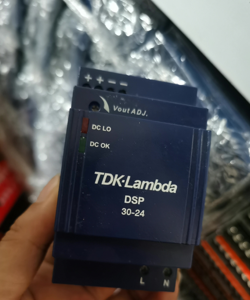

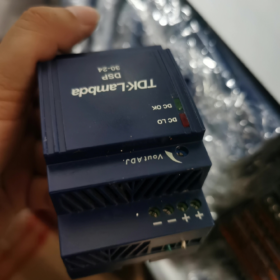
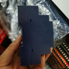
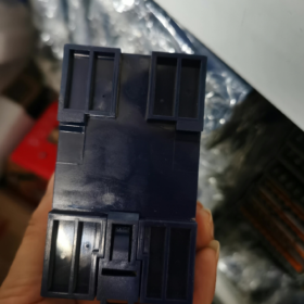
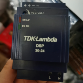
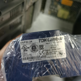
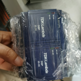
DSP DIN rail AC-DC power supply, DSP30-24, rated output 24VDC / 30W class, DIN35 rail mounting, Class II double insulation, no protective earth terminal required
- Core Electrical Specifications
Input
AC: 90~264VAC, 47~63Hz (wide input voltage for global use)
DC input compatible: 120~370VDC
Built-in PFC, compliant with EN61000-3-2
Cold-start inrush current: 25A@115VAC /50A@230VAC
Output
Rated voltage: 24VDC, adjustable range 24~28VDC via potentiometer
Rated current: 1.3A, rated power 31.2W
Voltage regulation accuracy: ±1%; ripple & noise: 50mV (20MHz bandwidth)
Protection functions: Overcurrent protection (110~160%, fold-back current limiting, short-circuit protection), overvoltage protection 30~36Vdc, overtemperature protection
Hold-up time: 25ms @115VAC input
Efficiency: Typical 83%~87%
- Mechanical & Environmental
Mounting: Standard 35mm DIN rail
Dimensions: W53mm × H95.5mm × D55.6mm
Weight: Approx. 200g
Cooling: Natural convection, fanless
Operating temperature: -25℃ ~ +71℃; derating starts above 61℃ (2.5%/℃)
Storage temperature: -25~+85℃; humidity 20~90%RH (non-condensing)
- Indicator LEDs & Terminal Definition
L: AC Line; N: AC Neutral
+: 24V Output Positive; −: Output Negative
Vout ADJ: Output voltage trim potentiometer
Green LED: DC OK (Output normal)
Red LED: DC LO (Undervoltage / Fault)
- Certifications & Safety
Safety standards: EN60950-1, UL60950-1, UL1310 Class2 output, CE/UKCA
EMC: EN55032 Class A; Immunity to EN61000-4 series
Isolation withstand voltage: 3kV AC
- Model Status & Replacements
DSP30-24 legacy model: NRND (Not Recommended for New Design); upgraded model DSP30-24/277A2, supports wider input 90~304VAC, direct rail replacement, verify pin definition before use
- Typical Applications
PLC, sensors, solenoid valves, small control cabinets, building automation, 24V industrial low-voltage power supply, ideal for compact cabinet installation.
- Common Troubleshooting
- Green LED off: Check AC input L/N, internal fuse, and minimum input voltage
- Red LED steady on: Output overload or short circuit; disconnect load to test power supply recovery
- Output voltage too high/low: Adjust Vout ADJ potentiometer
- Voltage drop under high temperature: Exceed derating temperature; reduce load or improve cabinet ventilation
- Domestic Compatible Alternatives
Meanwell: DR-30-24 (30W, DIN rail)
Delta: DRP-24V30W
Mornsun: LI30-24B24
DSP30-24 (DSP30-24VDC) Application Cases
Core advantages: Slim depth (only 56mm), Class II double insulation without PE, fanless natural cooling, wide input voltage, well suited for wall-mounted small electrical boxes and slim control cabinets; rated 24V 1.3A, recommended total load power ≤25W for derating margin
Case 1: Building Management System (BMS) / HVAC Control (OEM Primary Application)
Loads: Small DDC controllers, temperature & humidity transmitters, differential pressure sensors, electric damper actuators, room panels
System Description: Slim wall-mounted low-voltage cabinet, DSP30-24 DIN-rail mounted locally to supply HVAC field I/O modules and sensors. Class II design eliminates PE wiring and simplifies cabling.
Selection Notes: Total current of multiple sensors + small dampers <1A; full power available if cabinet temperature ≤61℃.
Typical Sites: Office buildings, shopping malls, hospital air handling units, fresh air unit local control cabinets.
Case 2: Access Control & Security / Fire Alarm Systems
Loads: Access controller, door contacts, card readers, fire alarm input modules, sounder beacons, zone modules
System Description: Wall-mounted security/fire control cabinet, AC220V feeds DSP30-24, 24VDC output powers access host and alarm modules. Wide 90~264VAC input provides tolerance against grid voltage fluctuation. Built-in short/overcurrent protection prevents host damage from field wiring short-circuit.
Note: Not for fire main backup power loops, used for auxiliary monitoring and access control subsystems only.
Case 3: Small Industrial Automation Cabinets (Standalone Stations)
Loads: Micro PLC (Siemens S7-200SMART, Mitsubishi FX3U compact CPU), proximity sensors, photoelectric sensors, relay modules, small solenoid valves
System Description: Local control cabinet for assembly line stations, inspection benches, small conveyors. One PLC + 4~8 sensors + 2~3 small solenoid valves.
Caution: Solenoid valves draw high inrush current, reserve margin for surge current during load calculation; recommended total steady-state load ≤25W.
Suitable for: Sorting stations, inspection equipment, small packaging machine local controls.
Case 4: Remote Monitoring & IoT Data Acquisition Cabinets
Loads: RTU, data acquisition modules, 4G/5G gateways, pressure/level transmitters, wireless sensors
System Description: Remote acquisition cabinets for water, heat, oil & gas sites or equipment rooms. Wide input range and -25℃ cold-start capability for non-constant-temperature environments.
Features: Fanless natural convection, no wearing parts, maintenance-free for unattended sites.
Case 5: Small Intelligent Lighting Control Systems
Loads: DALI lighting gateway, dimmer modules, 24V lighting bus sensors
System Description: Wall-mounted control cabinets for shopping malls and conference rooms, power supply for lighting bus controllers. Low profile fits slim lighting distribution boxes.
Case 6: Test & Measurement / Laboratory Small Tooling
Loads: Test fixture I/O boards, signal conditioning modules, sensor signal transmitters
System Description: Simple production test benches and small laboratory measurement cabinets. Stable 24V DC with low ripple, ideal for transmitter powering.
Selection & Application Limitations (Engineering Key Points)
- Max continuous output: 31.2W /1.3A, engineering design recommended derate to 80% (≤25W)
- Derating required when ambient temperature>61℃; further reduce load for high cabinet temperature
- Fanless design; reserve ventilation gaps on left/right, do not stack tightly beside circuit breakers
- NRND legacy model; use DSP30-24/277A2 for new designs; DSP30-24 only for spare replacement on existing equipment
- Class II double insulation, no PE wire required, simplifies wiring for many wall-mounted low-voltage cabinets, but not applicable for safety loops beyond extra-low voltage safety requirements
Typical Wiring Topology Reference
AC L/N → DSP30-24 → 24V+ /24V→ Parallel loads: PLC/DDC + Sensors + Relay modules; recommend fuse and surge absorber on output side to protect inductive loads such as solenoid valves.
DSP30-24 Engineering Selection Checklist
Applicable for: TDK-Lambda DSP30-24 (24VDC 31.2W, DIN rail, Class II, natural cooling)
Purpose: New project evaluation / field retrofit / spare part verification; legacy NRND model, use DSP30-24/277A2 for new projects
✅ 1. Load Power & Current Verification (Core)
Rated: 24V, 1.3A, 31.2W; recommended 80% derating limit: 25W /1.04A
- Sum steady-state loads
Sum rated current of all 24V devices: PLC, DDC, sensors, transmitters, relays, gateways, etc.
Inductive loads (solenoid valves, small actuators): inrush current must be considered, not only steady-state value
Total steady-state current ≤1.04A (recommended); short peak up to 1.3A, not continuous
- Load type restrictions
✅ Suitable: Transmitters, proximity/photoelectric switches, small I/O, RTU, access controllers, DALI gateways
⚠️ Use caution: High-power solenoid valves, large actuators, heating loads, motors
❌ Prohibited: Direct battery float charging (no charge management), high-power LED constant-current boards
- Output side protection selection
Recommended series fuse at output: 2A slow-blow fuse (24V side)
Inductive loads (solenoid / damper actuators): Freewheeling diode or RC snubber across coil to suppress back EMF and prevent power supply damage
Long cable runs: Add 24V-rated TVS for surge protection
✅ 2. Input Side Verification
- AC input voltage: 90~264VAC, 47~63Hz; compatible with DC 120~370VDC
Sites with large voltage fluctuation (old factories): Confirm minimum field voltage ≥90VAC
- Input wiring: L Line, N Neutral; Class II, PE earth not required for power supply
Note: Cabinet shell should connect to protective earth for EMC, power supply itself does not require PE
- Input inrush current: 25A@115VAC; 50A@230VAC
When multiple power supplies switch on simultaneously in one distribution box, select MCB carefully to avoid tripping at switch-on
✅ 3. Ambient Temperature & Derating Verification (Common Pitfall)
Operating temperature range: -25℃ ~ +71℃
Derating rule: Derating starts above 61℃ at 2.5%/℃
Example: Cabinet temperature 66℃, 5℃ above 61℃ → 12.5% power derating, max available power=31.2×(1-0.125)=27.3W
Engineering recommendation: Reserve extra margin if cabinet temperature>55℃, ideally keep ≤60℃
- Installation ventilation requirements
Minimum gap top/bottom ≥10mm; left/right ≥5mm clearance
❌ Do not mount tightly next to heat-generating components such as breakers and contactors
❌ Do not enclose inside fully sealed airtight boxes
- Storage temperature: -25~+85℃, power off
✅ 4. Mechanical Installation Verification
- Mounting: Standard 35mm DIN rail, vertical installation (terminals upward)
Horizontal / upside-down mounting not recommended; worsens heat dissipation and accelerates derating
- Dimensions: W53 × H95.5 × D55.6 mm; preferred for slim cabinets
- Vibration & shock: Suitable for general industrial and building automation; add rail lock for heavy machinery with high vibration
✅ 5. Protection Function Verification (Fault Modes)
Built-in protections: Fold-back current limiting / short-circuit protection, overvoltage protection, overtemperature protection
Protection behavior: Hiccup mode on some versions; auto-recovery after fault removal
- Overcurrent: 110~160% rated current, fold-back limiting
- Overvoltage protection: Trigger at 30~36VDC
- Overtemperature protection: Shutdown on overtemperature, auto retry after cooling
Note: Repeated short-circuit / thermal cycling shortens service life; output fuse should not be omitted
✅ 6. Status Indicators Verification
DC OK (Green): Output healthy
DC LO (Red): Undervoltage / overload / short-circuit fault
Vout ADJ potentiometer: Output adjustable 24~28VDC
Commissioning tip: Do not turn voltage up to 28V upper limit under no-load; re-measure voltage with load connected to avoid overvoltage damage to transmitters
✅ 7. EMC, Isolation & Safety Verification
- Isolation rating: Class II double insulation, input-output isolation withstand 3kV AC
- EMC: EN55032 Class A; immunity meets EN61000-4 (ESD, burst, surge)
⚠️ Class A: For industrial environments; not recommended for residential environments due to EMI non-compliance risk
- Certifications: UL/CE/UKCA; safety standard EN60950-1
- Cabling: Route 24V DC cables away from 220V AC power cables to reduce coupling interference
✅ 8. Model Lifecycle Verification (Critical Engineering Reminder)
DSP30-24: NRND Not Recommended for New Design
For repair & replacement on existing equipment: DSP30-24 acceptable
New projects: Upgrade to DSP30-24/277A2, input 90~304VAC, direct DIN rail replacement, verify terminal definition
Alternative domestic models: DR-30-24, LI30-24B24
✅ 9. Site Commissioning Procedure (Power-up Sequence)
- Disconnect all loads, power supply alone, measure no-load output voltage, trim Vout ADJ to 24V
- Connect loads gradually, monitor output voltage, temperature rise and LED status
- Perform short-circuit test (short duration), confirm hiccup protection activates and auto-recovers after fault removal
- Run full load for 30min, check housing temperature rise for abnormal heating
- Check voltage drop on long wiring runs; slightly increase output voltage to compensate for cable drop if wire gauge is thin or distance is long
📋 Quick Tick List (Copy directly to Excel)
| Verification Item | Requirement | Remarks |
| Total steady-state load power | ≤25W (80% derating) | Include inrush for inductive loads |
| Cabinet ambient temperature | Full power ≤61℃; derate above 61℃ | Measure cabinet internal temp, not room ambient |
| Input voltage range | 90~264VAC | Record minimum site voltage |
| Installation ventilation clearance | Top/bottom ≥10mm, left/right ≥5mm | Do not mount adjacent to heat sources |
| Output protection components | 2A slow-blow fuse, snubber for inductive loads | |
| Mounting orientation | DIN rail vertical mount, terminals upward | Upside-down impairs heat dissipation |
| Project type | Existing maintenance / New design | DSP30-24 not recommended for new projects |



NH42-63-318x560.png "CHINT PC-type automatic transfer switches (ATS)NH42-63/4SZ")



