 Contator,disjuntor,sensor,Codificador,CLP,Conversor

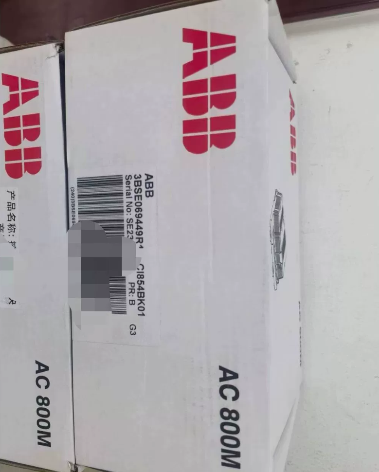

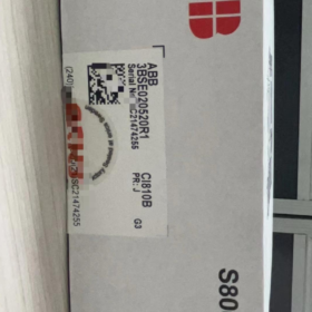
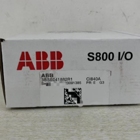
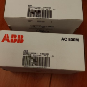
Código de pedido: 3BSE069449R1
Nome do modelo: CI854BK01
Nome completo do produto: PROFIBUS-DP/V1 Communication Interface Kit
Sistema Aplicável: AC800M / 800xA DCS
Kit Contents: CI854B communication module + TP854 baseplate
Código HS: 8517620000
Origem: Suécia
Peso líquido: 0.7 kg
Dimensões: 185 × 59 × 127.5 milímetros (A × L × D)
Especificações Técnicas Principais
- Protocolo de ônibus: PROFIBUSDP / DP-V1, PROFIBUS Master
- Bus Baud Rate: Até 12 Mbit/s
- Portas: Dual isolated PROFIBUS RS485 interfaces, supporting bus line redundancy
- Redundancy Capability
Line Redundancy: Dual bus ports, automatic switchover upon bus cable breakage
Master Redundancy: Two CI854BK01 modules can form PROFIBUS master redundancy, compatible with AC800M CPU redundancy
- Compatibilidade do sistema: 800xA 6.0.3.2 and later versions, Compact Control Builder 6.0.0-2+
- Dispositivos de campo: Connect S800 I/O, drives de frequência variável, valve positioners and various PROFIBUS DP field instruments; PROFIBUS PA bus can be extended via LD800P gateway
- Montagem: Montagem em trilho DIN, hot-swap capable (module can be replaced while powered on)
Aplicação principal
PROFIBUS DP master communication card for AC800M controller. It connects the DCS controller to PROFIBUS fieldbus to collect data from remote I/O, drives and field instruments, and send control commands. Widely used in power, químico, óleo & gás, paper and other process control projects.
Comparação de modelos (Key for Selection)
CI854BK01 (3BSE069449R1): Kit = CI854B module + TP854 baseplate
CI854AK01 (3BSE030220R1): Legacy version. Hardware and firmware differ and cannot be directly interchanged.
Diretrizes para solução de problemas
- Bus LED flashing: Check termination resistors, bus shield grounding and station address conflict
- Module not ready: Check TP854 baseplate contact, CEX bus power supply, firmware version matching with 800xA system
- Redundancy switchover failure: Verify redundancy pairing parameters and independent isolation of two physical bus links
Opções alternativas
Same platform upgrade: CI855 can be evaluated for new PROFIBUS interface on AC800M (note firmware and 800xA version compatibility)
Protocol replacement: CI871A for PROFINET applications
ABB 3BSE069449R1 (CI854BK01, CI854B + TP854 Baseplate) Guia de instalação
For AC800M / 800xA DCS, PROFIBUS DP/V1 dual line redundant communication module
⚠️ ESD Protection: Wear anti-static wristband throughout operation; power off before operation to avoid CEX bus interface damage
- Preparação de pré-instalação
- Desligar: Fully power down the AC800M controller, confirm no voltage on the rack and implement lockout-tagout
- Material Verification: CI854B module, TP854 baseplate, Type A purple PROFIBUS shielded cable, DB9 PROFIBUS connector with built-in termination resistor
- Ambiente: Install inside control cabinet on standard 35mm DIN rail; route away from high-power cables to avoid interference
- Validação: TP854 baseplate has coding lock which only matches CI854B to prevent wrong module installation
- Instalação Mecânica (TP854 Baseplate + CI854B Module)
- Mount TP854 Baseplate onto DIN Rail
Hook the rear latch of TP854 baseplate onto 35mm DIN rail and press down fully. The baseplate can be mounted side by side with AC800M PM8xx processor baseplate, on the left side of the processor. CEX bus connectors between adjacent baseplates are interlocked and fastened.
Opcional: TA526 wall mounting bracket for screw fixing (less common)
- Install CI854B Communication Module onto Baseplate
① Align bottom latches of module with the slots of TP854 baseplate
② Pivot the module inward with bottom as fulcrum until a click sound is heard for locking
③ Confirm full contact between module and baseplate to ensure reliable contact of internal CEX bus contacts
- Empty Slot Handling: Unused communication slots must be fitted with TA524 dummy module to maintain IP20 protection rating
Removal procedure in reverse: Press upper and lower latches of module, pivot outward to remove module; then remove baseplate
- PROFIBUS DP Bus Wiring (TP854 Dual DB9: Porta A / Porta B, Line Redundancy)
TP854 baseplate is equipped with two DB9 female connectors for PROFIBUS line redundancy
DB9 Pin Definition (PROFIBUS Standard):
Pino3: Linha B (RxD/TxD-P, Vermelho)
Pino 8: Linha A (RxD/TxD-N, Verde)
Escudo: Crimped to DB9 metal shell, single-point grounding to protective earth of control cabinet
Etapas de fiação:
- Use Type A purple PROFIBUS shielded twisted pair cable, connect shield to DB9 metal housing
- Single line: Connect Port A only; Line Redundancy Scheme: Connect Port A and Port B to two independent PROFIBUS buses respectively
- Termination Resistor Setting (Crítico)
If CI854BK01 is the end node of this PROFIBUS physical segment: Set built-in termination resistor on DB9 connector to ON (220Oh)
Middle node of segment: Set termination resistor to OFF; Only two ends of one PROFIBUS segment can enable termination resistors
- Cabling Specification: Route PROFIBUS cables separately from power cables; shield shall be earthed at one single point in cabinet only. Multi-point grounding is forbidden to prevent ground loop current.
- System-side Hardware Configuration (Control Builder M)
- Add CI854BK01 module in controller hardware tree, verify module version and firmware version
- Import GSD files of all PROFIBUS slave devices
- Set PROFIBUS address, taxa de transmissão (max 12Mbps) and slave I/O mapping
- Redundancy Configuration:
Line Redundancy: Single module with dual bus A/B, automatic switchover upon bus breakage
Master Redundancy: Two sets of CI854BK01 in rack, primary/backup mode with AC800M CPU redundancy
- Download hardware configuration to AC800M controller and power on
- Power-on Check and Commissioning
- Power on and observe CI854B front panel LEDs:
Run LED steady ON: Module healthy, CEX bus communication normal
Fault LED flashing: CEX bus fault, configuration mismatch, PROFIBUS bus fault or slave loss
- Bus Test: Use bus diagnostic tool to check signal-to-noise ratio of PROFIBUS segment and online status of all stations
- Redundancy Test (Line Redundancy): Disconnect Port A and Port B separately to verify communication continuity
- Notas importantes
- CI854B is powered by CEX bus. No external 24V power supply required for module itself
- Hot-swap supported: CI854B module can be plugged/unplugged online while system runs (TP854 baseplate cannot be hot swapped)
- Do not apply voltage to unused DB9 pins, which will burn out the module immediately
- Máximo 12 pcs CI854B modules can be installed on one AC800M controller, each acting as independent PROFIBUS master
- Common Installation Errors
- Termination resistors all ON or all OFF → Unstable bus and random slave drop-off
- Multi-point grounding of shield → Heavy interference and intermittent communication dropout
- Poor interlock of CEX bus between baseplates → Module fault alarm and cannot be recognized
- Line A/B reversed (Pin3/Pin8 swapped) → PROFIBUS communication failure
ABB 3BSE069449R1 (CI854BK01) Communication Parameter Configuration
Software Platform: Control Builder M (CBM), AC800M + 800xA System; Module works as PROFIBUS DP/DP-V1 Master, supporting Line Redundancy, dual DB9 ports Port A / Porta B
Pré-requisitos
- Hardware installation completed, reliable CEX bus interlock of TP854 baseplate, PROFIBUS bus cable crimped
- Collect corresponding GSD files of all field slaves (S800 I/O, Inversores de frequência, valve positioners)
- Confirm firmware version: CI854B firmware compatible with CBM project and 800xA system version
- Proteção ESD; controller can remain online (module supports hot-swap configuration download)
- Import GSD Files (Etapa 1)
- Open Control Builder M → `Tools` → `Fieldbus Manager`
- Select `Import GSD`, select GSD files of all slave devices and complete import
- After import, corresponding field device models can be found in PROFIBUS device catalog
- Add CI854BK01 Module in Hardware Tree
- Open hardware configuration tree of AC800M controller
- Right-click CEX bus slot → `Insert Module`, select CI854BK01 (3BSE069449R1)
- Double-click CI854B module to open communication parameter configuration window
- Core PROFIBUS Master Parameters (CI854B Property Page)
| Parâmetro | Descrição & Valor recomendado |
| Master Station Address | PROFIBUS master address, padrão 0. Must be unique within segment, cannot conflict with slaves |
| Taxa de transmissão | Opções: 9.6k / 19.2k / 93.75k / 187.5k / 500k / 1.5M / 3M / 6M / 12Mbit/s |
| ✅ Use 187.5k for commissioning by default; 12Mbps only for short distance and low interference. Lower baud rate for longer cable length | |
| DP Profile | DP-V0 (Basic cyclic I/O) / DP-V1 (Acyclic diagnostic read, HART instruments). Select DP-V1 for smart instruments |
| Line Redundancy Toggle | ✅ Enable: Automatic switchover between Port A and Port B dual bus; disable for single bus scheme |
| Slot Time / Tslot | Time slot, bus response timeout; auto-calculated normally, can be increased manually for long bus segments |
| Retry Count | Communication retry times, padrão 2; adjustable for high-interference sites |
| Watchdog Time | Slave watchdog time, must match field device setting |
Importante: Line redundancy only refers to bus link redundancy. For primary/backup module master redundancy, install two CI854BK01 on rack and configure Master Redundancy (paired with CPU redundancy)
- Add PROFIBUS Slaves, Configure Slave Parameters + I/O Mapping
- Right-click CI854B PROFIBUS bus node → `Insert PROFIBUS Device`, select field slave from GSD catalog
- Double-click slave: Set Slave Address, hardware DIP switch on site must match software setting, unique address within segment (1~125)
- Enter slave module configuration: Select I/O module type and map Process Data
Entrada: Field → Controller (%IW)
Saída: Controller → Field (%QW)
- DP-V1 devices: Configure acyclic channel for reading device diagnostics and parameter read/write (valve positioners, transmissores inteligentes)
- Add all slaves sequentially; máximo 125 slaves per CI854B
- Redundancy Parameter Breakdown (Two Redundancy Modes)
Modo 1: Line Redundancy (Single CI854BK01, Dual Bus Port A+Port B)
- Check `Line Redundancy` in CI854B properties
- Port A and Port B connect two independent PROFIBUS buses to the same set of slaves (slaves must support dual-port redundancy such as S800 I/O with redundant DP interface)
- Module automatically switches link upon bus breakage without interruption; no standby module
⚠️ Ordinary single-port DP slaves cannot be directly connected to line redundancy. RLM01 redundancy link module is required
Modo 2: PROFIBUS Master Redundancy (Dual CI854BK01, paired with AC800M CPU Redundancy)
- Redundant rack: Primary rack CI854BK01 + Backup rack CI854BK01
- Enable `Master Redundancy` in CBM and set master/backup synchronization parameters
- Backup CI854BK01 takes over PROFIBUS master automatically upon primary module failure; applied to high-reliability processes (poder, químico)
- Compile, Verify and Download Parameters
- Project Compile: `Build`, check errors. Focus on address conflict, mismatched I/O length and incorrect GSD version
- Online Download: Download hardware configuration and communication parameters to AC800M controller
- Após o download, observe CI854B front panel LEDs
Run steady ON: Module ready, PROFIBUS master normal
Fault flashing: Bus fault, slave dropout or parameter mismatch
- Bus Diagnosis: Check online status of all slaves and message error counter in CBM fieldbus diagnosis interface
- Comissionamento & Verification Steps
- Single bus test: Disconnect Port B, confirm all slaves stay online; then disconnect Port A to verify line redundancy switchover
- Read-write test: Force output signal and cross-check field instrument feedback; read input signal to verify mapping correctness
- Bus stress test: Monitor bus error counter; acceptable only if no continuous increment
- DP-V1 devices: Read device diagnostic information to confirm acyclic communication works
- Common Parameter Configuration Errors
- Duplicate master/slave address → Bus crash and persistent Fault alarm
- Over-high baud rate with long cable and poor shielding → Random slave drop and continuous increase of message errors
- Line Redundancy not enabled while dual bus wired → Redundancy switchover unavailable
- Mismatch between process data length and slave GSD → Slave fails to enter data exchange state
- Attempt to access acyclic parameters of DP-V1 instruments under DP-V0 mode → Diagnostic communication failure



NH42-63-318x560.png "Chaves de transferência automática tipo PC CHINT (ATS)NH42-63/4SZ")



