 Contator,disjuntor,sensor,Codificador,CLP,Conversor


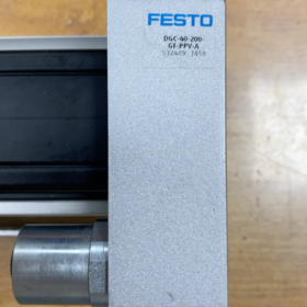
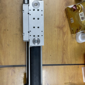
Detalhamento do código do modelo
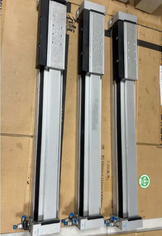
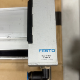
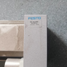
Material Não.: 532449 = Base part number for standard DGC series rodless cylinder com 40 mm furo
`DGC-40-600-G-PPV-A`
- DGC: Mechanical rodless linear actuator (steel band sealed rodless cylinder)
- 40: Piston bore diameter Ø40 mm
- 600: Effective stroke 600 milímetros
- G: Basic slide without integrated guide (piston slide only, no built-in guiding system. External linear guide is mandatory to bear loads and tilting moments)
GF: Integrated plain bearing guide; KF: Integrated recirculating ball bearing guide; G: Basic version without guide
- PPV: Adjustable pneumatic end cushioning on both ends, throttle-controlled damping at stroke limits
- UM: Built-in sensor grooves on both profile sides for mounting SME/SMT proximity switches for position detection
- Especificações Técnicas Principais
2.1 Pneumatic Performance
Operação: Dupla ação
Pressão operacional: 1.5 ~ 8 bar (0.15 ~ 0.8 MPa), rated working pressure 6 bar
Theoretical push/pull force at 6 bar: 754 N
Porto aéreo: G1/4 on side of both end caps
Amortecimento: Independently adjustable PPV air cushion at both ends
Maximum operating speed: ≤3 m/s
Repetitive positioning accuracy: ±0.1 mm (only valid with external guiding support)
2.2 Carregar & Moment Limits (Critical for G Version without Built-in Guide)
The G variant has no integrated guide. All radial forces and tilting moments must be absorbed by an external linear guide; the cylinder only transmits axial thrust:
Allowable static radial load Fy/Fz: 1380 N
Allowable tilting moments: Mx: 28 N·m; My: 54 N·m; Mz: 33 N·m
2.3 Ambiental & Material Data
Médio: Seco, filtered compressed air per ISO 8573-1 [7:-:-]
Temperatura ambiente: -10 ~ +60 °C (modelo padrão, non-explosion-proof)
Selos: NBR / PU polyurethane
Perfil & slide: Liga de alumínio extrudado; sealing band: aço inoxidável
Corrosion resistance class: CRC1, suitable for standard indoor automation environments
Conformidade: RoHS, Certificado CE
2.4 Weight Data (DGC-40-G)
Base weight at zero stroke: 2113 g
Weight increase per 10 curso mm: 49 g
Total weight of this 600 mm stroke model: 5053 g
Moving mass of slide: 732 g
- Estrutura & Instruções de instalação
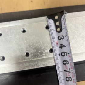
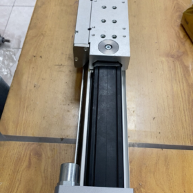
- Opções de montagem: Standard T-slots on bottom and side faces of the extruded profile, compatible with T-slot nuts, HPC foot brackets and flange accessories
- Sensor mounting: Continuous sensor grooves on both sides of the profile, compatible with SME-8 / SMT-8 magnetic switches
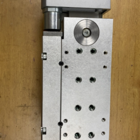
- Positioning reference: Mating locating pin holes on top and side surfaces of the slide for fixture alignment
- Stroke limit configuration: No mechanical hard stops as standard; additional hydraulic shock absorbers (YSR series) or mechanical stoppers are required
- Entrega padrão & Acessórios opcionais
Standard Included Components
Main cylinder unit DGC-40-600-G-PPV-A
Cushion adjustment screws on both ends
M8 mounting threaded holes on slide top face
Continuous sensor grooves (magnetic switches not included)
Acessórios opcionais comuns
- Position feedback: SME-8M-DS-24V-K-2,5-OE magnetic proximity switch
- Suportes de montagem: HPC-40 foot support, ZBH locating bushings
- End-of-stroke damping: YSR-20-20 hydraulic shock absorber for two-end limiting
- Stroke clamping unit: 1H-PN (holds position when air supply cuts off)
- Pneumatic fittings: QS-1/4-8 push-in tube connector
- Aplicativo & Diretrizes para seleção de modelos
Aplicações adequadas
X-axis long-stroke feeding, transfer and door actuation for automated machinery
Embalagem, marcenaria, machine tool loading/unloading, reciprocating coating axes
Light-load mechanical systems equipped with separate external linear guides
Selection Pitfalls for G Variant
1.-G` has no integrated guide. It cannot bear lateral forces or tilting moments independently. An external linear rail is mandatory; de outra forma, the sealing band will wear rapidly and the slide may jam.
- For heavy loads, high precision or large tilting moments, upgrade to DGC-40-600-KF-PPV-A (integrated recirculating ball guide with zero clearance and greatly improved load capacity).
- For strokes longer than 1000 mm running at high speed, add intermediate HPC support brackets to prevent profile deflection.
- Install protective bellows accessory for dusty environments or applications with cutting fluid splashes.
- Direct Replacement Models with Same Bore & AVC
- High-precision integrated guide alternative: DGC-40-600-KF-PPV-A (derived from same part number series 532449)
- Cost-effective plain bearing guide alternative: DGC-40-600-GF-PPV-A
- Compact short-stroke substitute: DGPL series guided rodless cylinder
- Domestic equivalent alternatives: Airtac HTD40×600, SMC MY3B40-600
- Falhas Comuns & Manutenção
- Stick-slip motion / insufficient thrust: Cushion throttle fully closed, insufficient supply pressure, foreign debris trapped on sealing band
- Vazamento de ar: Worn end cap seals, damaged stainless steel band, aged cushion screw sealing rings
- Slide jamming: Deformation caused by excessive lateral load, misalignment without external guiding
- Ciclo de manutenção: Maintenance-free up to 5000 km under standard operating conditions; clean and lubricate the sealing band every 2000 km in dusty environments
Overall Installation Dimensions of Festo DGC-40-G-PPV-A (Número da peça. 532449)
- Cross-section Profile Dimensions (Valid for All Strokes, Unidade: milímetros)
1.1 Profile Overall Width & Altura
Total profile width B1 = 111.5
Total profile height H1 = 40
Height from bottom mounting reference surface to sealing band centerline: 55.75
1.2 T-slot Mounting Grooves (Fundo & Side Faces Identical)
T-slot opening width T1=13.5, groove depth 2.1 milímetros, inner groove width 18 milímetros
Compatible T-slot nut: M8 standard type
1.3 Air Port Specification
G1/4 ports on both end cap sides; port center height from bottom surface: 16 milímetros
1.4 Dual-side A-type Sensor Grooves (Full-length)
Groove width 6 milímetros, profundidade 8 milímetros, fits SME-8 / SMT-8 magnetic switches
- Slide Mounting Dimensions (DGC-40-G Slide without Built-in Guide)
- Total slide width: 111.5 milímetros (matches profile width)
- Height of slide top mounting surface H3=93.8 mm
- Top fixture mounting threads
4 main threaded holes M8, thread depth 9 milímetros
Central locating pin hole D1=Ø9 H7 (match with ZBH-9 locating bushing)
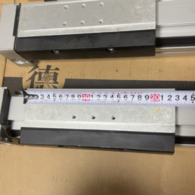
- Overall slide length L1=278.4 mm
- Clearance for cushion travel: Single-side pneumatic cushion travel length 29.5 milímetros (PPV cushion)
- Overall Cylinder Length Calculation Formula
Fixed end cap extension length L2=258 mm for DGC-40-G
Total cylinder length L_total = Stroke + L2 = Stroke + 258 milímetros
For this 600 mm stroke model:
L_total = 600 + 258 = 858 milímetros
End Cap Related Dimensions
Distance from outer face of each end cap to extreme cushioned slide position: 29.5 mm per side
Protrusion length of side-mounted cushion adjustment screw: 8 milímetros
M6 tapped holes on both end caps for mounting HPC-40 foot brackets
- Matching Dimensions for HPC-40 Foot Support Brackets (Base Padrão)
Center distance between mounting holes on foot bracket: 90 milímetros
Fastening bolt: M8, locked via profile T-slots
Single bracket thickness: 19 milímetros; brackets used in pairs at both ends
- Critical Clearance & Space Reservation Requirements
- Full slide travel range: 0 ~ 600 milímetros
- Single-side cushion occupied travel: 29.5 mm → usable mechanical contact stroke = 600 29.5×2 = 541 milímetros
- Minimum clearance reserved at both ends for cushion adjustment operation: ≥15 mm
- Maximum allowable protrusion height of fixture bolts on slide top: ≤6 mm to avoid scratching the sealing band
- Quick Reference Dimension Table (Unidade: milímetros)
| Parâmetro | Value for DGC-40-G |
| Profile width B1 | 111.5 |
| Profile height H1 | 40 |
| Height of slide mounting surface H3 | 93.8 |
| Overall slide length L1 | 278.4 |
| Fixed end cap extension L2 | 258 |
| Total length for 600 curso mm | 858 |
| Single-side pneumatic cushion travel | 29.5 |
| Fixture mounting threads | 4×M8 |
| Locating pin hole | Ø9 H7 |
| Rosca da porta aérea | G1/4 |
| Compatible T-slot bolt | M8 |
- Precauções de instalação
1.-G` variant has no integrated guide. The cylinder body is only fixed by bottom T-slots; all lateral loads must be supported by an external linear guide.
- Total length of 600 mm stroke unit is 858 milímetros. For horizontal mounting under heavy load, add one intermediate HPC-40 support bracket to prevent profile sagging.
- M8 fixture screws on slide top must not be screwed deeper than 9 milímetros, to avoid damaging internal piston assembly.
- Magnetic switches are inserted into full-length A-type grooves on both sides; switches can be installed at any position along the full 600 curso mm.





NH42-63-318x560.png "Chaves de transferência automática tipo PC CHINT (ATS)NH42-63/4SZ")



