 Contator,disjuntor,sensor,Codificador,CLP,Conversor

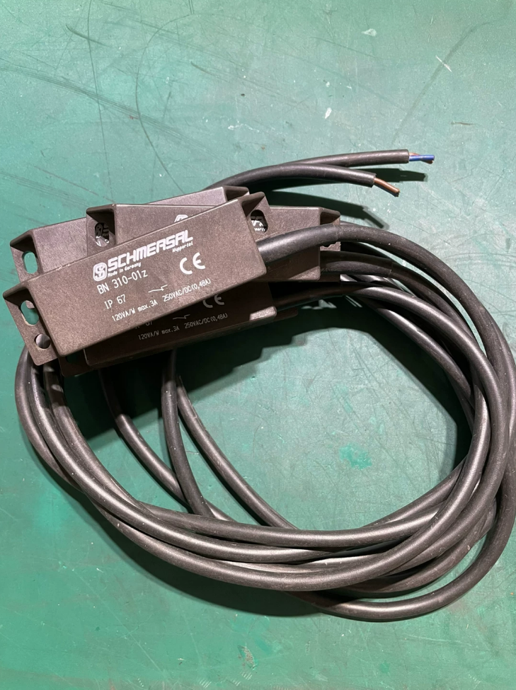

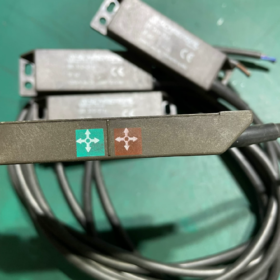
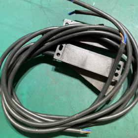

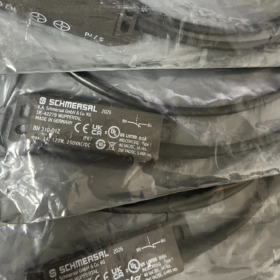
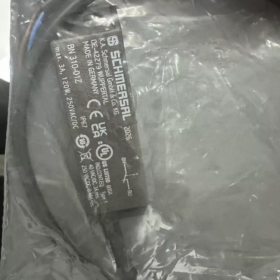
Informações Básicas
- Marca & Origem: SCHMERSAL, Alemanha
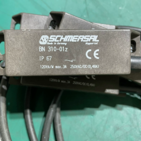
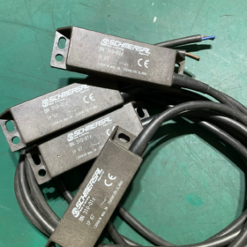
- Modelo completo não.: BN 310-01Z
- Factory Order Codes:
1m standard cable version: 101133844
BN310-01Z 3.0m cable version: 101180919
- Tipo de produto: Único normalmente fechado (NC) Reed Magnetic Proximity Switch (Safety Door Interruptor Magnético)
- Princípio Operacional: Contact-free magnetic actuation with hermetically sealed reed contacts; used with dedicated magnetic actuators
- Núcleo Elétrico & Especificações Mecânicas
2.1 Avaliações de contato
Configuração de contato: 1 Normally Closed contact (01Z = single NC)
Tensão máxima de comutação: AC250V / CC250V
Corrente máxima de comutação: 3UM
Rated Switching Power: 120VA (AC) / 120C (CC)
Operate/Release Delay: 0.3~0.6ms; Max Switching Frequency: 300Hz
Vida útil mecânica: ≥1 billion switching cycles
2.2 Dimensões Gerais & Fiação
Dimensão da Habitação: 88milímetros (eu) × 25mm (C) × 13mm (T)
Cable Spec: 2-core PVC cable H03VV-F, cross-section 0.75mm²
Comprimento padrão do cabo: 1eu; Optional extended lengths: 3m/5m/10m
Material da Habitação: Glass-fiber reinforced thermoplastic, slim flat design
Peso líquido: 75g
2.3 Proteção Ambiental & Condições Operacionais
Classe de Proteção: IP67 (à prova de poeira, protected against splashing water, suitable for dusty & humid workstations)
Faixa de temperatura operacional: -25℃~+75℃
Resistência à vibração: 10~55Hz, amplitude 1mm; Resistência ao choque: 30g/11ms
Modo de atuação: Sensor magnético lateral; Distância de detecção efetiva: 3~60 mm (depende do modelo de atuador correspondente)
Precisão de posicionamento repetido: ±0,3mm
2.4 Certificações
CE, cULus; Compatível com EN IEC 60947-5-2; Certificação especial para indústria de elevadores
- Explicação do código do modelo
BN310 01 Z
BN310: Série de interruptores reed planos finos
01: 1 conjunto de contato
Z: Normalmente fechado (NC) saída de contato
Comparação da Mesma Série
BN310-01Z: NC único (amplamente utilizado para circuitos de segurança)
BN310-10Z: Único normalmente aberto (NÃO)
BN310-RZ: Contato de mudança (1NÃO+1NC)
- Definição de fiação (2-cabo central)
Fio Vermelho S/rd: Um terminal de contato reed
Fio Azul N/gn: O outro terminal de contato reed
Lógica de circuito:
Aproximações magnéticas → Contato fecha; O ímã se afasta → O contato abre (O circuito de segurança NC é cortado, máquina para)
- Cenários típicos de aplicação
- Monitoramento de posição para portas de proteção & capas protetoras em máquinas-ferramentas e linhas de produção automatizadas
- Porta do carro / detecção de posição de porta de patamar para elevadores (compatível com os padrões originais do elevador)
- Monitoramento de intertravamento de portas de segurança para máquinas de embalagem, injection molding machines and conveyors
- Contact-free position signal collection for small equipment cabinet doors and safety shields
Vantagens: No mechanical wear, óleo & splash water resistant, ultra-long service life, compact mounting footprint
- Acessórios correspondentes & Diretrizes de seleção
- Only SCHMERSAL original BN-series magnetic actuators (BP10N/BP10S etc.) are allowed; generic magnets cause unstable sensing distance
- IP67 rating tolerates washdown environments, yet permanent submersion is prohibited; install away from strong electromagnetic interference sources
- Safety circuit applications are recommended to be wired in series with safety relays to meet machinery safety standards
- Alternative Models within the Series
Compact short-distance variant: BN20 series
Changeover contact solution: BN310-RZ
Extended cable options: BN310-01Z 3M/5M/10M
SCHMERSAL BN310-01Z Magnetic Safety Switch Installation Manual
Informações do documento
Modelo: BN310-01Z (1Interruptor magnético de palheta único normalmente fechado NC)
Padrões de fábrica: E IEC 60947-5-2, EM 1088 padrão de porta de segurança
Equipamento aplicável: Portas de segurança para máquinas-ferramenta, patamar do elevador/portas do carro, intertravamentos automatizados de proteção de máquinas
Usuários-alvo: Engenheiros elétricos qualificados, instalação de equipamentos & técnicos de manutenção
- Regras obrigatórias de segurança pré-instalação
- Segurança Elétrica
Toda a fiação, os trabalhos de desmontagem e montagem devem ser realizados com corte total de energia; a conexão a quente de cabos é estritamente proibida. Os circuitos de segurança devem ser emparelhados com relés de segurança da série SCHMERSAL SRB/AES para atender aos requisitos de monitoramento de segurança.
- Uso obrigatório de acessórios originais
Somente atuadores magnéticos originais da série BP da SCHMERSAL (BP10/BP15/BP20/BP31/BP34/BP21) são permitidos. Ímãs genéricos de alta resistência levam a falsas comutação, precisão degradada e vida útil drasticamente reduzida.
- Restrições de materiais para superfícies de montagem
Chaves e atuadores não devem ser montados diretamente em placas de aço ferromagnéticas. Para bases de montagem em aço, almofadas espaçadoras não ferromagnéticas com espessura ≥20mm (plástico/alumínio/cobre) deve ser montado; caso contrário, a distância de detecção será severamente reduzida.
- Requisitos à prova de adulteração
Para aplicações em portas de segurança, parafusos de segurança anti-torx devem ser usados para evitar curto-circuito intencional dos circuitos de segurança. A chave e o atuador nunca devem servir como batentes mecânicos para evitar rachaduras no invólucro sob compressão.
- Limites Ambientais
Temperatura operacional: -25℃~+75℃; A proteção IP67 resiste à lavagem com respingos, a submersão permanente é proibida. Mantenha-se afastado de fontes de alta EMI, como inversores, contatores e eletroímãs de alta potência.
- Especificações do produto & Dimensões
2.1 Parâmetros do corpo do interruptor
Perfil: Carcaça plana 88mm (eu) × 25mm (C) × 13mm (T)
Estrutura de montagem: Furos longos com fenda na parte superior & carcaça inferior para ajuste fino da distância de detecção para frente/trás
Cabo: 2-cabo de PVC núcleo H03VV-F, 0.75seção transversal mm²; padrão 1m, opcional 3/5/10m
Definição de cor do cabo: Vermelho = S, Azul = N (dois terminais de contato reed NC)
Capacidade de contato: AC250V/3A, 120VA; CC250V/3A, 120C
Precisão de posicionamento repetido: ±0,3mm; Vida Mecânica ≥1 bilhão de ciclos
2.2 Sn de distância de detecção padrão para atuadores correspondentes
| Modelo de atuador | Distância de detecção nominal | Distância de detecção combinada com atuador duplo |
| PA10 | 5milímetros | 17milímetros |
| PA15 | 6milímetros | 17milímetros |
| BP20/BP31 | 20milímetros | - |
| BP12 | 10~30mm | - |
| BP34 | 5~20 mm | - |
| BP21 | 25~50 mm | - |
- Procedimentos passo a passo de instalação mecânica
Etapa 1: Planejamento da posição de montagem
- Fixe a chave em estruturas de máquinas estacionárias, monte o atuador em portas/tampas de proteção móveis. É necessária atuação paralela lado a lado: a face de detecção da caixa deve estar alinhada com a superfície do atuador.
- Mantenha o espaçamento mínimo ≥50 mm entre vários interruptores BN310 em um gabinete para evitar interferência magnética mútua e disparo falso.
- As superfícies de montagem devem ser planas, sem rebarbas ou saliências, para evitar deformação do alojamento sob tensão.
Etapa 2: Montagem de espaçadores de isolamento (Obrigatório para Estruturas de Aço)
Estrutura de aço → almofada espaçadora não ferromagnética ≥20mm → corpo da chave BN310; instale espaçadores idênticos entre os painéis das portas de aço e os atuadores. A montagem direta sem espaçadores é permitida para alumínio, molduras de aço inoxidável ou plástico.
Etapa 3: Protegendo o corpo do switch
- Rosqueie os parafusos M3/M4 através dos orifícios de montagem e aperte-os frouxamente, sem apertar totalmente.
- Feche totalmente a porta de proteção, aproxime o atuador da face de detecção da chave e defina a folga nominal por modelo de atuador.
- Quando a porta está totalmente fechada, o atuador deve permanecer dentro da faixa de detecção nominal; quando totalmente aberto, a distância de separação deve exceder a distância máxima de liberação para garantir uma abertura confiável do contato.
- Ajuste a posição através de furos ranhurados, testar lógica de comutação, em seguida, aperte totalmente os parafusos na diagonal com torque de 0,8 ~ 1,2 N·m; é proibido apertar demais que esmague a carcaça.
Etapa 4: Montagem do Atuador & Calibração de Alinhamento
- A superfície do atuador deve correr perfeitamente paralela à face de detecção do interruptor; inclinação superior a 10° causa falha completa.
- Com a porta fechada, o centro do atuador deve estar alinhado com o centro da zona de detecção do interruptor, deslocamento vertical ≤3mm.
- Garanta que não haja colisão ou atrito entre os cabos e o interruptor durante o percurso completo da porta; reserve a folga do cabo para evitar tensão quando a porta abre no ângulo máximo.
Etapa 5: Roteamento de cabos & Proteção
- Passe os cabos dentro de dutos de cabos ou tubos corrugados para evitar danos à bainha causados por bordas afiadas.
- Minimum cable bending radius ≥5× outer cable diameter; sharp right-angle folds are prohibited.
- Leave slack at cable entry to avoid tension pulling the switch; fit cable sleeves for workstations with cutting fluid or heavy oil contamination.
- Especificações de fiação elétrica
4.1 Core Wire Definition
BN310-01Z is a passive reed switch with single NC two-wire contacts, no auxiliary power supply required:
Red wire S: First contact terminal
Blue wire N: Second contact terminal
4.2 Lógica de circuito
Guard door closed (actuator in position): Contact closed, circuit conductive
Guard door open (actuator separated): Contact open, safety circuit interrupted, machine shuts down
4.3 Three Standard Wiring Schemes
Esquema 1: Safety Relay Safety Circuit (Recommended for Machine Tools & Elevadores)
Wire all BN310-01Z switches in series and connect to the input circuit of SRB safety relays:
Power supply AC230V / DC24V → Fios vermelho-azul conectados em série de todos os interruptores → Terminais de entrada do relé de segurança
Abrir qualquer porta de proteção interrompe o circuito; relé de segurança corta a saída para os contatores principais.
Esquema 2: Entrada Digital CLP (Contato Seco Passivo)
Para PLC tipo coletor NPN:
DC24V+ → Alternar fio vermelho; Alternar fio azul → terminal de entrada digital PLC X; Terminal COM comum do PLC conectado a 0V
Porta fechada: Canal de entrada energizado e indicador aceso; Porta aberta: Canal de entrada desenergizado.
Esquema 3: Circuito de relé de controle auxiliar
Linha viva AC220V → Alternar fio vermelho; Trocar fio azul → Bobina do relé; Terminal oposto da bobina conectado à linha neutra
Porta fechada: Bobina do relé energizada; Porta aberta: Bobina do relé desenergizada.
4.4 Proibições de fiação
- Não exceda a carga nominal AC250V/3A; nunca acione contatores de alta potência diretamente.
- Evite passar cabos de controle paralelos aos cabos de potência do inversor no mesmo duto; interferência eletromagnética causa desconexão intermitente.
- Comprimento do isolamento do fio limitado a 3 ~ 5 mm; evitar que fios de cobre perdidos entrem em curto-circuito; aperte totalmente os terminais para evitar superaquecimento.
- Testes obrigatórios de comissionamento pós-instalação
- Teste de continuidade de desligamento
Defina o multímetro para o modo de continuidade e conecte as pontas de prova ao vermelho & fios azuis. O alarme de continuidade soa quando a porta é fechada (atuador adjacente); nenhum sinal de continuidade quando a porta está totalmente aberta – lógica confirmada como normal.
- Teste de limite de lacuna
Com a porta fechada, atuador de deslocamento ±2 mm dentro da faixa de detecção nominal, mantendo a continuidade. Puxe gradualmente o atuador além da classificação Sn; o contato deve abrir de forma confiável sem travamento da histerese.
- Teste de ciclo de abertura/fechamento de curso completo
Abra e feche a porta repetidamente durante 50 ciclos; verifique se não há desconexão ou interferência aleatória; inspecionar cabos quanto a tensão ou abrasão.
- Teste de interferência eletromagnética
Ligue a máquina completa, iniciar/parar inversores e contatores; confirme nenhuma desconexão inesperada do switch. Se ocorrer um falso acionamento, aumentar a separação entre os cabos de controle e de potência ou instalar dutos blindados.
- Matriz de solução de problemas de falhas
| Fenômeno de falha | Causas Raiz | Ações Corretivas |
| Sem sinal com porta fechada, circuito permanentemente aberto | 1. Atuador com polaridade incompatível/invertida | Substitua pelo atuador original; ajuste espaçador não ferromagnético ≥20mm; recalibrar o alinhamento paralelo |
| 2. Faltando espaçador não ferromagnético na base de aço, sinal magnético insuficiente | ||
| 3. Atuador inclinado ou desalinhado | ||
| O contato permanece fechado com a porta aberta, perda da função de segurança | 1. Folga de fechamento excessivamente pequena causando adesão por histerese magnética | Aumentar a folga de fechamento da porta; mantenha um espaçamento ≥50 mm entre os interruptores; limpe detritos de metal da face do invólucro |
| 2. Cross-talk magnético entre vários switches | ||
| 3. Lascas de metal ferromagnético aderidas à superfície de detecção | ||
| Desconexão intermitente aleatória durante a operação | 1. Tensão do cabo / fratura de fio interno | Redirecione os cabos com reserva de folga; controle separado & fiação de energia; reaperte todos os fixadores de montagem |
| 2. EMI de cabos de alimentação adjacentes | ||
| 3. Parafusos de montagem soltos devido à vibração | ||
| Entrada de água na habitação & falha | IP67 resiste apenas a respingos, não submersão contínua; vedação danificada na entrada do cabo | Evite instalação subaquática; substitua os cabos danificados e sele o prensa-cabo com selante de silicone |
- Manutenção & Procedimentos de desmontagem
- Ciclo de manutenção regular
Estações de trabalho empoeiradas/oleosas: Inspeção mensal
Oficinas limpas e secas: Inspeção trimestral
Itens de inspeção: Aperto do parafuso, integridade da bainha do cabo, folga de detritos de metal na superfície de detecção.
- Processo de desmontagem
Corte totalmente a alimentação da máquina → Desconecte os terminais dos cabos dentro do gabinete de controle → Afrouxe os parafusos de montagem → Remova a chave e o atuador; nunca puxe os cabos com força para extrair componentes.
- Eliminação em fim de vida
Descarte como eletrônico & resíduos elétricos de acordo com os regulamentos locais; interrompa o uso imediatamente se o tubo de palheta de vidro interno rachar.
- Operações proibidas de instalação estrita
- Usando ímãs genéricos de terceiros em vez de atuadores originais da série BP da SCHMERSAL
- Montagem direta em superfícies de aço sem espaçadores de isolamento não ferromagnéticos
- Atuador de montagem inclinado em um ângulo em relação à face de detecção da chave
- Dobra acentuada ou tensão permanente aplicada aos cabos
- Executando fiação/desmontagem com energia energizada
- Espaçamento entre vários switches inferior a 50 mm
- Usando interruptor/atuador como batente mecânico que suporta cargas de impacto
- Conectando circuitos de segurança diretamente aos circuitos de alimentação principais sem supervisão do relé de segurança
- Lista de pedidos correspondentes de fábrica original
- Corpo do interruptor BN310-01Z (1/3/5/10m opções de cabo; código de pedido padrão de 1m: 101133844)
- Atuadores magnéticos correspondentes: PA10 / PA15 / BP20 conforme necessário
- Acessórios de montagem: 20espaçadores de isolamento de plástico mm, Parafusos de segurança anti-torx M4, tubos corrugados de cabo
- Relés de segurança de suporte: SRB300, AES1235





NH42-63-318x560.png "Chaves de transferência automática tipo PC CHINT (ATS)NH42-63/4SZ")



