 Contator,disjuntor,sensor,Codificador,CLP,Conversor

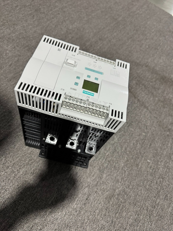

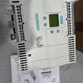
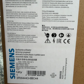
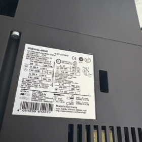
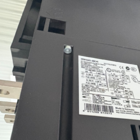
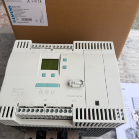
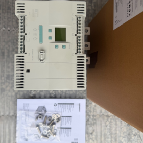
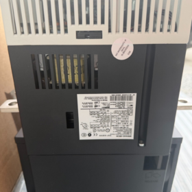
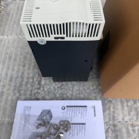
Detalhamento do código de pedido MLFB
3RW 44 43 6 BC 4 4
- 3RW: Série de produtos de partida suave SIRIUS
- 44: Bypass integrado de alto desempenho trifásico totalmente controlado partida suave (regulação tiristor independente por fase, contator de bypass integrado como padrão)
- 43: Código de tamanho, corrente nominal 203 Um em 40 °C para cargas padrão
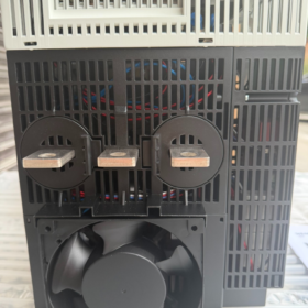
- 6: Tipo de terminal do circuito de controle = terminais de parafuso; circuito principal conectado através de barramentos de cobre
- B: Contator de bypass integrado (2/3-bypass de fase para perda zero durante operação em estado estacionário)
- C: Controle de tiristor trifásico independente (controle trifásico completo para equilibrar correntes trifásicas)
- 4: Tensão de alimentação de controle Us = AC 230 V
- 4: Tensão operacional do circuito principal Ue = AC 200~460 V
- Parâmetros elétricos principais (40 °C, Aula 10 Carga Padrão)
| Item | Valor do parâmetro |
| Corrente nominal para fiação padrão (motor conectado diretamente ao soft starter) | 203 UM |
| Potência do motor correspondente em 400 V | 110 KW |
| Corrente nominal para conexão interna-triângulo (enrolamentos do motor divididos em dois ramos) | 352 UM |
| Potência do motor correspondente em 400 V para fiação delta interna | 200 KW |
| Faixa de tensão do circuito principal | CA 200~460 V (50/60 Hz) |
| Fornecimento de controle | AC 230 V±10% |
| Modo de controle de fase | Tiristores antiparalelos por fase com regulação independente |
| Funções padrão | Contator de bypass integrado para desviar os tiristores durante a operação |
| Classe de disparo de sobrecarga padrão | Aula 10; Aula 10/20/30 configurável manualmente |
| Funções de proteção | Perda de fase, desequilíbrio de fase, sobrecarga do motor, superaquecimento, curto-circuito do tiristor, tempo limite de início, detecção de falha à terra |
| Expansão da comunicação | Compatível com Profibus DP (requer módulo de comunicação 3RW4900-0KC00) |
| Peso | Aprox.. 11.2 kg |
| País de origem | Alemanha |
III. Correspondência de carga & Limites de seleção
- Cargas Aplicáveis
Bombas de água, fãs, transportadores de correia, compressores de ar, refrigeradores, equipamento centrífugo (velocidade fixa, apenas é necessário iniciar/parar suavemente)
- Referência de Derating para Operação Pesada (40 °C)
Aula 20 serviço pesado (partidas frequentes, alto torque de partida): corrente permitida 170 UM, motor combinado 90 KW
Aula 30 serviço extra pesado (moinhos de bolas, trituradores): corrente permitida 145 UM, motor combinado 75 KW
- Condições Operacionais Proibidas
Regulação contínua de velocidade, comutação frequente para frente/para trás, corrida de alta frequência (≥30 vezes por hora)
- Estrutura de hardware & Descrição da fiação
- Circuito Principal: Terminais de barramento de cobre; Entrada lateral da linha L1/L2/L3, Saída lateral do motor T1/T2/T3; suporta fiação padrão e fiação delta interna
- Circuito de Controle: Terminais de parafuso para sinais de partida/parada, saídas de falha, reiniciar, entrada de termistor externo
- Painel do Operador: Display LCD integrado para configuração da rampa de partida, tensão inicial, parada suave, limite de corrente e limites de proteção
- Instalação: Montagem vertical na parede; mínimo 150 mm de folga superior/inferior para dissipação de calor; temperatura ambiente 0~40 °C (desclassificação para temperaturas acima 40 °C)
- Ciclo de vida do produto & Modelos de substituição
- Status: 3Série RW44 descontinuada (PLM: Fase de fim de suporte do PM490); fabricante original interrompe a produção em massa, apenas estoque de peças de reposição disponíveis
- Modelo de substituição direta OEM (Recomendado para novos projetos)
3RW5543-6HA14 (série 3RW55 de nova geração, mesmo 203 Uma corrente nominal, 230 Alimentação de controle V, 200-460 V tensão principal, terminais de parafuso, bypass integrado)
- Diferenças entre os antigos & Novos Modelos
Pegada menor, menor consumo de energia, Modbus RTU nativo e lógica de proteção otimizada para 3RW55
Diferentes dimensões de recorte de montagem; barramentos de cobre e suportes de montagem precisam de modificação durante a modernização do gabinete
- Dispositivos de proteção correspondentes recomendados
- Proteção contra curto-circuito do circuito principal: Disjuntor em caixa moldada compatível com 110 circuito do motor kW
- Proteção Especializada para Tiristores: fusível ultrarrápido aM/gR 500 V 315 UM (obrigatório a montante do soft starter, sem proteção contra curto-circuito do tiristor sem ele)
- Proteção Adicional do Motor: Termistor PTC externo conectável aos terminais de controle para proteção contra disparo excessivo do enrolamento
VII. Matriz típica de solução de problemas
| Sintoma de falha | Causa raiz | Solução |
| Alarme de superaquecimento durante a inicialização | Duto de ar de resfriamento bloqueado / temperatura ambiente acima 40 °C / inicialização de carga pesada de longa duração | Limpe a poeira, melhorar a ventilação do gabinete, atualize para um soft starter de classificação mais alta |
| Alarme de perda de fase | Perda de energia monofásica, conexão de barramento solta, enrolamento do motor quebrado | Aperte a fiação, medir a tensão de entrada trifásica e a resistência do enrolamento do motor |
| Corrente de partida irrestrita, saída direta de tensão total | Tiristores quebrados, contatos soldados do contator de bypass | Desconecte a fonte de alimentação para testar tiristores; substitua o módulo de contato de bypass |
| Tempo limite de inicialização | Tensão inicial muito baixa, carga mecânica apreendida, tempo de rampa insuficiente | Aumentar a tensão inicial, inspecionar carga mecânica, prolongar o tempo de rampa de partida |
VIII. Principais vantagens
- Regulação de tensão trifásica independente; elimina o desequilíbrio de corrente trifásico comum em soft starters bifásicos, prolongando a vida útil do rolamento do motor
- O bypass integrado elimina a perda de potência do tiristor durante a operação estável, entregando 98% economia de energia vs modelos sem bypass
- Suporta parada suave e supressão de golpe de aríete de parada da bomba, ideal para abastecimento de água, sistemas de drenagem e HVAC
- Proteção abrangente e integrada do motor, eliminando a necessidade de relés de sobrecarga térmica separados
Especificações de dimensão completa de Siemens 3RW4443-6BC44
- Dimensões gerais do equipamento (L × A × P, Unidade: milímetros)
210 (Largura) × 230 (Altura) × 298 (Profundidade)
- Recorte de montagem & Fixando Dimensões
- Distância central horizontal entre os furos de montagem: 167 milímetros
- Distância central vertical entre os furos de montagem: 190 milímetros
- Especificação do fixador: Parafuso M8, torque de aperto 15 N·m
- Largura mínima reservada do recorte do painel do gabinete ≥210 mm, altura ≥230 mm
III. Espaço mínimo obrigatório do gabinete para dissipação de calor (Suporte de parede vertical)
Folga superior: ≥100mm
Folga inferior: ≥75mm
Folga lateral (várias unidades lado a lado): ≥5mm
Superfície traseira do equipamento até a placa traseira do gabinete: contato direto permitido
- Dimensões externas da caixa (Armazenagem & Referência Logística)
348 × 433 × 394 milímetros, peso líquido 11.22 kg
- Notas Suplementares
- Classe de proteção: IP00; apenas para instalação em gabinete
- Todas as variantes 3RW4443 (-6BC34/-6BC44/-2BC45) compartilham dimensões gerais idênticas; diferenças apenas nos terminais de controle e tensão de alimentação
- O modelo de substituição 3RW5543-6HA14 ocupa menos espaço; recalcular o tamanho do recorte do gabinete para retrofits
Lista Completa & Definição de Função de Terminais de Controle – Siemens 3RW4443-6BC44
Este modelo está equipado com terminais de controle tipo parafuso, categorizados em cinco grupos: fonte de alimentação de controle, entradas digitais, sensor de temperatura PTC do motor, saídas de relé programáveis, relé de falha geral.
- Terminais de fonte de alimentação de controle (Fornecimento principal da unidade)
- A1, A2
Função: Fonte de alimentação de controle principal para soft starter
Avaliação do modelo: AC 230 V±10%, 50/60 Hz
Regra de fiação: A1 linha viva L, Linha neutra A2 N
- Educação Física
Terminal de aterramento protetor do circuito de controle; conectar ao barramento de aterramento do gabinete
- L+, eu-
Fonte auxiliar interna de 24 VCC integrada para chaves de entrada digitais passivas; externo 24 Fonte de alimentação V não necessária
L+ = pólo positivo DC24 V; L = pólo negativo DC24 V (terreno comum)
- 4 Terminais de entrada digital programáveis IN1 / IN2 / IN3 / IN4
Lógica: Conecte uma extremidade do switch a L+, a outra extremidade ao INx correspondente para acionar a função atribuída; todas as funções configuráveis através dos parâmetros do painel
Alocação padrão de fábrica
IN1: Partida do motor (Grupo de parâmetros 1 rotação para frente)
IN2: Não atribuído
IN3: Não atribuído
IN4: Reinicialização de falha
Todas as funções personalizáveis
Modo manual local, início de emergência, fluência em baixa velocidade, parada de emergência rápida, redefinição de falha, 3 grupos de comutação de parâmetros do motor direto/reverso
III. Terminais de detecção de temperatura do enrolamento do motor T1, T2
Para conexão de termistor PTC de motor externo (proteção contra superaquecimento do motor)
O soft starter desarma automaticamente quando a temperatura do enrolamento excede o limite
Curto-circuito T1 e T2 se não houver PTC instalado para desabilitar a proteção térmica
- 3 Saídas de relé programáveis independentes (Contatos secos passivos, CA250V / 5 UM)
Cada par consiste em contatos normalmente abertos com funções totalmente atribuíveis através do menu de parâmetros
- 13, 14 Saída 1
Padrão: Sinal de funcionamento do motor (fecha após a conclusão da inicialização e pull-in do contator de bypass)
- 23, 24 Saída 2
Padrão: Não atribuído; configurável para status de bypass, inicialização em andamento, pré-alarme, Frenagem CC, etc..
- 33, 34 Saída 3
Padrão: Não atribuído; personalizável para todos os tipos de sinais de status de equipamento
- Terminais de relé de falha geral 95, 96, 98 (Alarme de falha global)
3-contato de comutação de pólo para sinalização de falha unificada, amplamente utilizado em circuitos de segurança
95: Terminal comum COM
95-96: Normalmente fechado (NC): condutivo quando a unidade está saudável; abre em caso de falha
95-98: Normalmente aberto (NÃO): fecha quando ocorre uma falha, para luz indicadora de falha / fiação da buzina de alarme
Tabela de resumo do terminal
| Grupo Terminal | Número do terminal | Objetivo principal |
| Fonte de alimentação de controle | A1, A2 | Entrada de tensão de controle AC230 V |
| Terra Protetora | Educação Física | Aterramento do circuito de controle |
| Integrado 24 Fornecimento V | L+, eu- | Alimentação DC24 V para entradas digitais (positivo / chão) |
| Entradas Digitais | IN1, IN2, IN3, IN4 | Iniciar/parar, reiniciar, comutação de parâmetros, modo manual etc.. |
| Sensor de temperatura PTC | T1, T2 | Interface do termistor de superaquecimento do enrolamento do motor |
| Saída de relé 1 | 13, 14 | Status de funcionamento do motor (normalmente aberto) |
| Saída de relé 2 | 23, 24 | Status do equipamento personalizável (normalmente aberto) |
| Saída de relé 3 | 33, 34 | Status do equipamento personalizável (normalmente aberto) |
| Contato de mudança de falha | 95, 96, 98 | Alarme de falha global (COM + NC + NÃO) |
Diretrizes Complementares de Fiação
- Torque de aperto para fios de controle: 1.2~1,5 N·m; seção transversal do fio condutores de cobre de 0,75 ~ 1,5 mm²
- As entradas digitais são do tipo contato passivo; alimentação somente de L+/L interno sem PLC externo 24 Alimentação V
- Série normalmente fechada 95/96 contatos no circuito de segurança para cortar a alimentação do contator a montante em caso de falha
- A comunicação Profibus requer módulo 3RW4900-0KC00 separado com porta dedicada (não faz parte dos terminais de controle frontais)





NH42-63-318x560.png "Chaves de transferência automática tipo PC CHINT (ATS)NH42-63/4SZ")



