 Contator,disjuntor,sensor,Codificador,CLP,Conversor

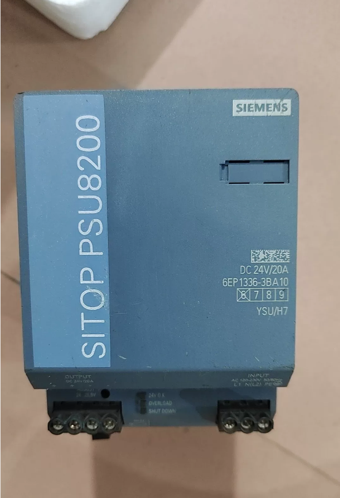

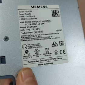
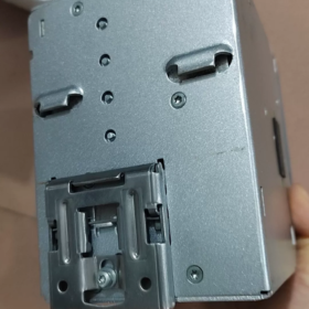
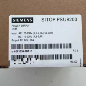
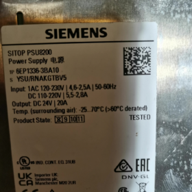
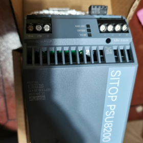
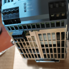
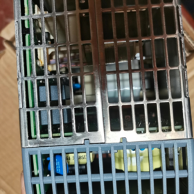
Pedido nº.: 6EP1336-3BA10
Designação Completa: SITOP PSU8200 /1ACDC /24VDC /20A DIN-rail Industrial Switch-Mode Power Supply
Saída: 24 VDC 20 A, 480 C; Supports parallel operation for power expansion and redundant operation
- Especificações elétricas principais
Entrada (Unique AC/DC dual-input for this model)
AC rated: 120-230 VAC, operating range 85-275 VAC, 50-60 Hz
DC rated: 110-220 V DC, operating range 88-350 VDC
Corrente de entrada: 2.5 A @230 VAC; 4.6 A @120 VAC
Hold-up time: ≥20 ms at rated load
⚠️ Power derating is required when input voltage<100 V
Saída
Nominal: 24 CCV / 20 UM
Faixa ajustável: 24.0-28.8 CCV (potentiometer on front panel for long-cable voltage drop compensation)
Power-Boost function: Up to 3× nominal current (60 UM) for inrush loads such as motor and relay startup; selectable constant-current mode or latching shutdown upon short-circuit
Galvanically isolated output; protection against short-circuit, sobrecarga, overvoltage and overtemperature; auto-recovery after over-temperature shutdown
Eficiência: aprox.. 93%-94%
Signal Terminals
- 24V-OK relay contact (13-14): Potential-free dry contact, closed when power supply operates normally, for PLC status diagnosis
- Remote on/off (15-16): Potential-free contact for external remote activation / deactivation of 24 V output
- Mecânico & Dados Ambientais
Montagem: Snap-on to standard DIN-rail, carcaça metálica, fan-less natural convection cooling
Dimensões: W90 mm × H125 mm × D125 mm
Peso: aprox.. 1.2 kg
Classe de proteção: IP20 (for cabinet-mount use only)
Temperatura operacional: -25℃~+70℃; derating above 60℃; máx.. 75 % load at 70 ℃
Heat dissipation clearance: ≥50 mm clearance top & fundo; units may be mounted tightly side-by-side
Certificações: CE, UL/cUL, CCC, GL marine approval, RoHS
III. Model Evolution & Opções de substituição
- Direct predecessor replacement: 6EP1336-3BA00 (descontinuado)
6EP1336-3BA10 is hardware-revamped version, pin-to-pin, dimension-to-dimension, function-compatible drop-in replacement, with higher efficiency and improved low-input-voltage performance.
- New-project new-generation SITOP PSU6200 series: 6EP3336-8SB00-0AY0
Observação: 6EP3336-8SB00-0AY0 supports AC-input only, no DC-input capability. Not hardware-compatible; terminal assignments differ, pay attention during selection.
- Compatible Extension Modules (PSU8200 Modular System)
Directly compatible with SITOP modular add-ons without extra adapters:
Buffer module: 6EP1961-3BA21; DC-UPS uninterruptible module
Módulo de redundância: 6EP1961-3BA00; for dual-power redundant supply
Selectivity module: 6EP1961-3BA31, multi-channel 24 V branch current-limiting protection; short-circuit on one branch will not collapse the whole 24 V busbar
- Cenários típicos de aplicação
Armários de controle PLC, robótica, máquinas-ferramentas, porta & equipamento marítimo, process automation. Ideal for systems requiring AC/DC dual-input (por exemplo. backup DC supply), altas cargas de irrupção, power-status feedback and remote on/off control.
- Diretrizes de fiação
- Terminais de entrada: L1, N(L2), Educação Física; supports single-phase AC, two-phase tap from three-phase mains, or DC input
- Saída: Dual sets of screw terminals for +24V and 0V. Parallel both sets when output current>15 A for current sharing and thermal prevention
- Signal terminals: 13-14 comentários sobre status; 15-16 remote on/off; both are potential-free contacts, do not connect high-voltage circuits
- Factory default output voltage is 24 V. Fine-tune to 26-28 V for long-cable drop compensation; do not exceed withstand voltage of downstream equipment.
Mounting Instructions for Siemens 6EP1336-3BA10 (PSU8200-20A)
- Tipo de montagem
Montagem padrão: EN 60715 compliant DIN-rail (TS35-7.5 / TS35-15, 35 mm rail) snap-in installation
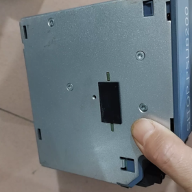
Built-in spring clip on rear side, tool-free mounting. Release lever at bottom; push lever down to remove unit from rail.
❌ Wall-mounting by direct screw fastening is NOT supported. DIN-rail mounting only.
Classificação de proteção IP20, apenas para instalação em gabinete interno; not for outdoor bare-field deployment.
- Orientação de montagem (Mandatory for thermal performance & vida útil)
Fan-less natural convection; orientation cannot be arbitrarily changed
- Standard position: montagem vertical, terminals facing down (entrada & output terminals at bottom of unit), unit upright. This is the only official position for continuous full-load operation.
- ❌ Proibido: horizontal side-mount, de cabeça para baixo (terminals up), tilted mounting. Non-standard orientations degrade cooling and require heavy load derating; not recommended for field deployment.
- Requisitos de liberação térmica (Crítico)
| Direção | Required Clearance | Observações |
| Principal | ≥50 mm | Allow upward hot‑air flow; cable trunking shall not occupy this space |
| Fundo | ≥50 mm | Cool‑air intake; trunking shall not block bottom area |
| Esquerda / Certo | 0 milímetros | Multiple units can be fitted tightly adjacent, no side‑to‑side gap required |
Do not mount heat-generating components directly above the power supply. Derate load when cabinet ambient>60 ℃.
- Montagem & Procedimento de remoção
- Hook upper latch of rear spring clip onto DIN-rail.
- Press lower section toward rail until an audible “click” confirms clip engagement.
- Shake gently to verify firm seating against vibration loosening.
- Remoção: Push down the black release lever at bottom, swing lower part outward, lift unit off rail.
For high-vibration environments: Fit DIN-rail end stops to prevent sliding displacement.
- Fiação Terminal & Torque Values
Execute a fiação com a energia desconectada.
Input L/N/PE: 0.2-4 mm² conductors, tightening torque 0.5-0.6 N·m
Output +24V /0V: Dual terminal pairs; parallel both pairs for currents>15 A for heat mitigation
Signal terminals 13-14 (OK feedback), 15-16 (Remote on/off): 0.14-1.5 mm² fine wires, torque 0.5-0.6 N·m
- Mounting for Parallel / Redundancy Modules
This power supply can be installed side-by-side tightly on DIN-rail with compatible SITOP extension modules (redundância, buffer, selectivity modules). No side-to-side thermal gap needed between power supply and add-on modules.
- Proibições de montagem
- Do not install unit inside enclosed bottom trunking in cabinet; blocked top/bottom clearance leads to over-temperature shutdown.
- Forbid upside-down or horizontal installation.
- Do not place heat-intensive devices directly above the unit.
- Indoor cabinet-use only; avoid open-air and high-humidity unprotected environments.
6EP1336-3BA10 (PSU8200-20A) Paralelo / Redundancy Guidelines + Troubleshooting Checklist
- Parallel Operation for Power Expansion (No Fault Isolation)
Máx.. 5 identical units in parallel for automatic current sharing. Dip-switch A must be set ON to activate parallel characteristic curve.
- Hardware prerequisites: Identical order number 6EP1336-3BA10; keep hardware revisions consistent if possible.
- Requisitos de fiação
Connect +24 V and 0 V of each unit to common output busbar. Positive cables shall have identical length and cross-section to equalize impedance for proper current sharing.
All 0 V negative terminals must be commonly grounded; floating ground is not permitted.
Common input circuit-breaker recommended for synchronized start-stop.
No-load output voltage difference between individual units ≤50 mV (factory default meets requirement; recalibrate if potentiometers have been adjusted).
- Dip-switch settings
A-ON: Parallel mode (for power expansion)
A-OFF: Single-unit mode (padrão de fábrica; do NOT leave OFF for parallel operation)
- Limitação: Direct parallel for power expansion cannot isolate faults. Short-circuit on one output will pull down the whole 24 V busbar. Not for fault-tolerant redundancy.
- 1+1 Redundant Supply (Fault-isolated, Recommended Engineering Solution)
Two PSU8200-20A units plus Redundancy Module 6EP1961-3BA00 (PSE202U) for decoupling isolation. Se uma fonte de alimentação falhar, the second takes over the load seamlessly without 24 V bus interruption.
- DIN-rail layout: Two power supplies + redundancy module mounted tightly adjacent; terminals all face down; no side-to-side clearance required.
- Pontos-chave da fiação
- Feed two power supplies from independent input circuits for maximum redundancy reliability.
- Connect 24 V+ output of each power supply to the two input channels of the redundancy module.
- Reliably bond 0 V terminals of both power supplies and redundancy module for equipotential connection; this step is mandatory.
- Route redundancy-module output to field 24 V load busbar.
- The redundancy module provides fault relay contacts, connect to PLC digital input for redundancy-fault alarm.
- Dip-switch setting: For redundant configuration, set dip-switch A of power supplies to OFF (single-unit mode). Do NOT activate parallel mode.
⚠️ Never implement redundancy by direct parallel without redundancy module. Internal short-circuit of one unit will crash the whole 24 V system.
III. LED Indicator Reference Table
| Status do LED | Significado | Ação |
| Verde constante LIGADO | Unit healthy, output>20 V | Operação normal |
| Yellow steady ON | Sobrecarga / constant‑current limit active, Power‑Boost triggered | Verifique a corrente de carga; locate partial short‑circuit; reduzir a carga |
| Red steady ON | Latching shutdown (curto-circuito / sobretensão / temperatura excessiva) | Power‑off for ≥60 seconds, or de‑assert Remote 15‑16 for ≥5 s for reset; eliminate short‑circuit / over‑heat root cause |
| All LEDs OFF | No input supply; internal fuse blown | Verify AC/DC input voltage and PE grounding |
Dip-switch B: Short-circuit response selection
B-OFF (padrão de fábrica): Constant-current mode, 23 A short-circuit limiting; auto-recovery after fault clears; yellow LED lit
B-ON: Latching shutdown mode; output cuts off upon short-circuit; red LED lit; power-cycle reset required
- Troubleshooting Checklist
- No LED indication after power-on, zero output
- Measure input L-N voltage: AC 85-275 VAC / DC 88-350 VDC; confirm PE protective earth connection.
- Check screw terminal torque for loose contacts; verify upstream circuit-breaker status.
- If input voltage is normal but no LED lights: Internal input fuse failure; falha de hardware, replace power supply.
- Yellow LED steady ON, output drops to 18-20 V
- Load current exceeds 20 A → constant-current limiting mode; measure actual total load current.
- Partial short-circuit or cable insulation damage on output side. Desconecte todas as cargas; check if voltage recovers to 24 V under no-load condition.
- Excessive voltage drop caused by long-distance thin-gauge cables; use larger-size output conductors or slightly raise output voltage via potentiometer for compensation.
- Red-LED latching shutdown on power-on, sem saída
- Output-side short-circuit. Test with all loads disconnected; normal no-load behavior indicates external load short-circuit.
- Excessive cabinet ambient temperature, insufficient top/bottom ventilation clearance triggering over-temp protection; confirm ≥50 mm top & bottom clearance.
- Output overvoltage: Ensure potentiometer is not accidentally adjusted above 28.8 V; confirm downstream-device voltage withstand rating.
- Reset procedure: Power-off ≥60 s then re-energize; or open Remote 15-16 for ≥5 s then close again.
- Abnormal 24V-OK (13-14) relay contact behavior
Terminais 13-14 are potential-free dry contacts, closed only when output>20 V. Avaliação de contato: DC30 V, máx.. 0.1 UM. For PLC digital-input signal only; do NOT drive contactor coils or high-power loads.
- Poor current-sharing in parallel; one unit runs excessively hot
- Dip-switch A not set to ON.
- Large discrepancy in length / cross-section of positive output cables.
- No-load output voltage difference>50 mV between units; fine-tune potentiometers for matching.
- Loose 0 V wiring leading to equipotential mismatch.
- Remote terminals 15-16 fail on / off control
15-16 are potential-free contacts: Short-circuit = output enable; open-circuit = output disable. No external supply required.
If remote function is unused: Keep 15-16 short-circuited with factory jumper; do not remove jumper.
- Recomendações de comissionamento
- New cabinet commissioning: Power-on without load first; confirm 24 V output and steady green OK LED; connect loads incrementally.
- Redundancy-system commissioning: Disconnect one input source at a time; verify seamless switch-over with zero load dropout.
- High-temperature cabinet applications: Apply load derating above 60 ℃ ambient; avoid continuous full-20-A operation.





NH42-63-318x560.png "Chaves de transferência automática tipo PC CHINT (ATS)NH42-63/4SZ")



