 Contactor,întrerupător de circuit,senzor,Codificator,PLC,Convertor

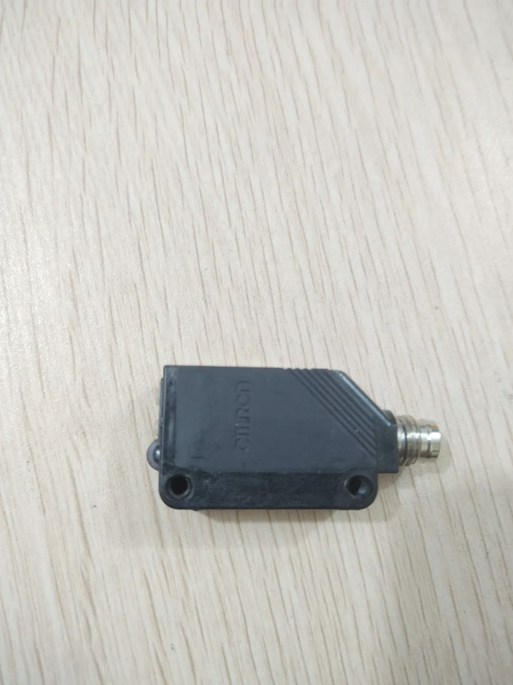

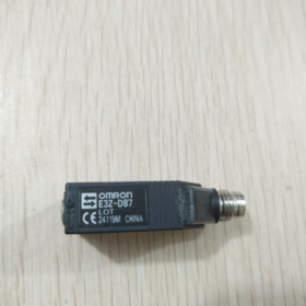
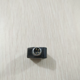
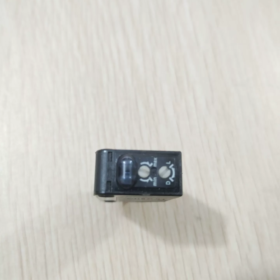
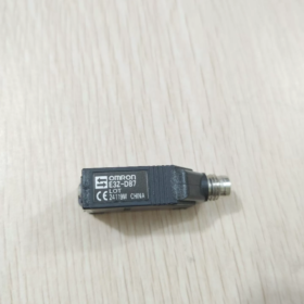
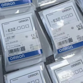
E3Z: Compact builtinamplifier senzor fotoelectric serie
D: Diffusereflective detection
8: Ieșire PNP (6 = NPN output)
7: M84pin connector, longrange diffusereflective type (2 = cableout type)
Specificații tehnice de bază
| Articol | Caietul de sarcini |
| Metoda de detectare | Diffuse‑reflective |
| Sursă de lumină | LED infrarosu, 870 nm |
| Distanța de detectare standard | 1000 mm (300×300 mm white paper) |
| Ieșire | Ieșire tranzistor PNP, max. load 100 mA |
| Modul de operare | Light‑ON / Dark‑ON selectable (L/D DIP switch) |
| Alimentare electrică | DC 12‑24 V ±10% |
| Timp de răspuns | ≤1 ms (act / reset) |
| Conexiune | M8 4‑pin male connector; mating cables: XS3F‑M421‑402‑A (2 m straight), XS3F‑M422‑402‑A (2 m angled) |
| Protecție la intrare | IP67 |
| Materialul carcasei | Plastic de inginerie PBT |
| Temperatura de operare | ‑25 ℃ ~ +55 ℃ (no icing or condensation) |
| Funcții de protecție | Reverse‑polarity protection, output short‑circuit protection, mutual‑interference resistance |
| Indicatori | Portocale: Operation indicator; Verde: Stability indicator |
M84pin Pinout (Sensorside male connector)
- Maro: DC24V+
- Alb: Mode select (LON/DON)
- Albastru: 0V GND
- Negru: Ieșire semnal PNP
L switch = LightON (output turns ON when object approaches); D switch = DarkON (output turns ON with no object). Singleturn potentiometer on side adjusts sensitivity.
Related Series Selection Guide
- E3ZD67: Funcție identică & distanta de detectare, Ieșire NPN, conector M8 (NPN counterpart of D87)
- E3ZD82: PNP, 1 m diffusereflective, 2 m fixed prewired cable, no connector
- E3ZD87IL3: IOLink enabled version; hardware parameters otherwise identical
Aplicații tipice
Objectpresent detection on conveyor lines, inposition detection, part counting, utilaje de ambalare. Suitable for target identification up to 1 m. Diffusereflective performance is affected by object color / reflectivitate; effective distance decreases significantly for darkcolored targets.
Instalare & Note de punere în funcțiune
- Avoid highly reflective backgrounds; keep backgrounds well away from the sensor’s maximum sensing range.
- Adjust the potentiometer until the green stability indicator stays ON, indicating sufficient sensing margin.
- When multiple sensors are mounted sidebyside, offset their angles to prevent mutual optical interference.
- Ensure M8 connector sealing against water and oil contamination.
OMRON E3ZD87 Fault Lookup Table
Pin recap: 1 Brown DC24V+|2 White LON/DON mode|3 Blue 0V|4 Black PNP output
Indicator definition: Green = Stability indicator; Orange = Operation indicator. Infrared LED is invisible to human eyes — do not search for visible red light.
| Simptom de eroare | Cauze posibile | Troubleshooting Action |
| Power‑on: both green and orange indicators OFF | 1. No supply voltage / insufficient voltage | 1. Measure voltage between pin 1‑3 at sensor connector: must be DC12‑24 V |
| 2. Polaritate inversă a puterii | 2. Swap brown and blue wires | |
| 3. Oxidized / loose M8 pins, cablu rupt | 3. Test with a known‑good M8 cable | |
| 4. Internal power circuit damage (supratensiune / water ingress) | 4. If still no indicators after cable replacement → sensor defective, înlocuiți unitatea | |
| Green indicator stays ON; orange indicator never changes with/without target | 1. Target beyond sensing range | 1. Reduce sensing distance; turn potentiometer clockwise for higher sensitivity |
| 2. Sensitivity potentiometer set too low | 2. Toggle L/D switch | |
| 3. Wrong L‑ON/D‑ON switch setting | 3. Remove nearby reflective background surfaces | |
| 4. Poor reflectivity of dark target | 4. Dark‑colored objects yield much shorter effective range | |
| 5. Interference from reflective background | ||
| Orange indicator lights, but PLC receives no signal | 1. Incorrect PNP output wiring; black pin 4 not connected to PLC input | 1. Confirm PLC input module type for PNP logic |
| 2. Wrong PLC input common‑terminal wiring (PNP requires PLC input common tied to 0 V) | 2. Verify black‑wire loop; do not leave floating | |
| 3. Output load exceeds 100 mA rating | 3. Locate short‑to‑ground fault; power‑cycle to clear protection | |
| 4. Output short‑circuit protection triggered | ||
| Indicators flicker; unstable detection, false triggering without target | 1. Optical crosstalk between adjacent photoelectric sensors | 1. Angle sensors away from one another |
| 2. Uneven surface reflectivity of target | 2. Turn potentiometer counter‑clockwise to lower sensitivity | |
| 3. Excess sensitivity picking‑up background reflection | 3. Route cables away from power lines; clean lens window | |
| 4. Power‑supply fluctuation; cable routed alongside power cables | 4. Check 24 V power‑supply ripple | |
| 5. Praf / oil contamination on lens window | ||
| Green indicator OFF; only orange indicator ON | Insufficient sensing margin, operating near detection limit, unstable under field conditions | Increase sensitivity or shorten sensing distance. Reliable operation requires steady‑ON green indicator. |
| Works normally after power‑on, fails after runtime; recovers when cooled | 1. Temperatura ambientală prea ridicată | 1. Confirm ambient temperature within ‑25~+55 ℃ |
| 2. Large voltage drop on 24 V supply under load | 2. Measure actual voltage at sensor under loaded condition | |
| 3. Internal sensor aging | 3. If fault recurs consistently, replace sensor |
Standard Quick Bench Test (Verify sensor hardware health)
- Use knowngood M8 cable: pin 1 Brown to 24V+, pin 3 Blue to 24V; leave pin 2 White and pin 4 Black completely unconnected (floating).
- Apply power: Green stability indicator must illuminate.
✅ Green ON: Sensor hardware OK. Fault lies in field wiring, PLC logic, cabling or mounting environment.
❌ Green OFF: Sensor internally damaged; replace sensor.
Note importante
- E3ZD87 is PNP output. Do not treat as NPN, otherwise indicators work but PLC receives no signal.
- Pin 2 White floating = default LightON; shortto0V selects DarkON. Do NOT connect pin 2 to 24V+.
- Greenindicator OFF means insufficient sensing margin. Even if orange indicator toggles, field falsetrigger risk is high. Always commission for steadyON green indicator.
OMRON E3ZD87: How to Judge Exceeded Sensing Range
Nominal rating: 1000 mm maximum with 300×300 mm white paper. Effective range reduces sharply for lowreflectivity darkcolored targets.
Indicator definition: Green = stability margin indicator; Orange = operation output indicator
Method 1: Indicatorbased check (fieldfriendly, no tape measure)
- Turn sensitivity potentiometer fully clockwise for maximum sensitivity.
- Move real target toward sensor starting from far distance.
Case A: Orange operation indicator turns ON, but green stability indicator never lights
👉 Operating beyond reliable usable range. Detection is marginal; vibratie, dust or minor target offset can cause signal loss. Do not use at this distance.
Case B: Target approaches; orange indicator ON AND green stability indicator stays steadily ON
👉 Within valid working range with adequate sensing margin. Acceptable for operation.
✔ Commissioning rule: At working position, green indicator must stay steadily ON. OrangeON / greenOFF = marginal / overrange condition.
Method 2: Distance test (using whitepaper reference target)
- Use 300×300 mm whitepaper target; potentiometer set to maximum sensitivity.
- Gradually increase gap between sensor and paper:
1000 mm: No target detection regardless of potentiometer adjustment; orange indicator remains OFF → beyond nominal range.
8001000 mm zone: Possible intermittent orange flicker, green indicator OFF. This is marginal zone; avoid for engineering deployment.
Practical engineering recommendation: Keep actual working distance 0700 mm to preserve safety margin.
Method 3: Distinguish true overrange vs poortargetreflectivity
Diffusereflective sensors do not have fixed cutoff distance. Target color changes effective sensing distance.
White paper: aproximativ. 1000 mm max
Grey workpiece: aproximativ. 500700 mm
Black rubber / mattedark workpiece: effective distance may drop to only 200400 mm
Quick discrimination test: Place white paper at your working gap.
① White paper triggers greenON; realworkpiece does NOT → Sensor hardware fine; low target reflectivity creates effective overrange. Scurtați distanța de montare.
② White paper also fails to light green → Physical gap exceeds sensor capability.
Common Misdiagnosis Scenarios
- Reflective background (perete / metal behind target): Green indicator stays ON due to background reflection, yet real workpiece cannot be detected.
👉 Remedy: Increase gap between workpiece and background, or reduce sensitivity.
- Potentiometer turned too low: Physical distance is acceptable but green indicator remains OFF.
👉 Before range assessment, always turn potentiometer fully clockwise to max sensitivity.
Stepbystep field assessment procedure
- Potentiometer set to maximum sensitivity; set to LightON mode; clean lens window.
- Place actual workpiece at intended operating position.
- Observe indicators:
✅ Green + Orange both ON → Distance acceptable
❌ Only Orange ON, Green OFF → Marginal / overrange; must reduce installation gap
❌ Orange never activates → Gap exceeds sensor detection capability
Nota: This sensor has no numerical distance readout. Range can only be assessed via indicator status. IOLink variant E3ZD87IL3 provides quantitative signalstrength values.
Factors Affecting Sensing Distance of OMRON E3ZD87 Diffusereflective Photoelectric Sensor
Nominal 1000 mm is specified under reference conditions: 300×300 mm white paper, maximum sensitivity, no background interference. Realworld effective distance is affected by multiple factors below.
- Target Object Properties (Dominant factor)
- Culoare & reflectivitate
Alb / brightlightcolored: High reflection, near nominal 1000 mm
Gri: Reduced effective distance
Negru, mattedark, cauciuc: Weak infrared reflection; effective distance may drop to 200400 mm
- Target size
Targets smaller than sensor spot return less light; max usable distance shortens. Detection may fail completely if target is smaller than spot size.
Reference test target is 300×300 mm white paper. Small workpieces experience range reduction.
- Surface material & texture
Polished mirror surfaces: Reflected light may miss receiver window, causing unstable detection.
Rough diffuse surfaces: Good detection performance.
Translucent / transparent objects: Infrared passes through; return signal weakens, range drops heavily.
- Incident angle
If target surface is not roughly perpendicular to sensor optical axis, reflected light deflects away and effective range decreases. Mount so target faces sensor approximately squarely.
- Sensorside Settings & Stare
- Sensitivity potentiometer
Clockwise = higher maximum sensing distance; counterclockwise = shorter maximum sensing distance.
Do not run at fullmax sensitivity in production, risk of pickingup background reflections. Always aim for steadyON green stability indicator.
- Lens contamination
Praf, cutting fluid, oil mist, water film on lens attenuate light intensity, shorten sensing distance and trigger false detection. Maintain lens cleanliness.
- Ambient & Background Conditions
- Reflective background behind target
Metal panels, white walls behind target may be detected instead of workpiece. Sensor appears to have long range but cannot detect actual parts.
Remediu: Increase separation between workpiece and background, or lower sensitivity.
- Optical crosstalk between adjacent sensors
Multiple E3Z units mounted close can interfere optically, causing erratic readings and anomalous range performance. Offset mounting angles and spacing.
- Strong ambient light
Direct sunlight or bright incandescent light hitting receiver window overwhelms infrared signal, shortening usable range or causing detection failure. Prevent direct stronglight incidence.
- Electric & Operatingcondition Influences
- Tensiune de alimentare
Supply below 12 V reduces infraredLED output power and shortens sensing range. Measure voltage at the sensor M8 connector, not only at powersupply cabinet.
- Temperatura mediului ambiant
At upper temperature limit near +55 ℃, LED luminous efficiency drops, slightly reducing max sensing range. Low temperature down to 25 ℃ has minor impact.
- Cable voltage drop
Long M8 cables create voltage drop, indirectly lowering LED drive and reducing effective range.
Practical Engineering Guidelines
- Nominal 1000 mm is ideallab condition. Do not design projects around the full 1000 mm rating.
Lightcolored targets: Recommend ≤700 mm operating gap
Dark / black targets: Recommend ≤400 mm operating gap
- Judge usability by indicator status, not datasheet nominal distance: Green indicator must stay ON at working position. OrangeON / greenOFF = marginal insufficient margin.
Quick Fault Differentiation
White paper triggers greenON at working position; real workpiece does NOT → Effective overrange due to poor target reflectivity.
Even white paper fails to light green indicator → Physical gap exceeds sensor capability, or lens fouling / tensiune de alimentare insuficientă.





NH42-63-318x560.png "Comutatoare de transfer automat de tip PC CHINT (ATS)NH42-63/4SZ")



