 Contactor,întrerupător de circuit,senzor,Codificator,PLC,Convertor


Informații de bază despre produs
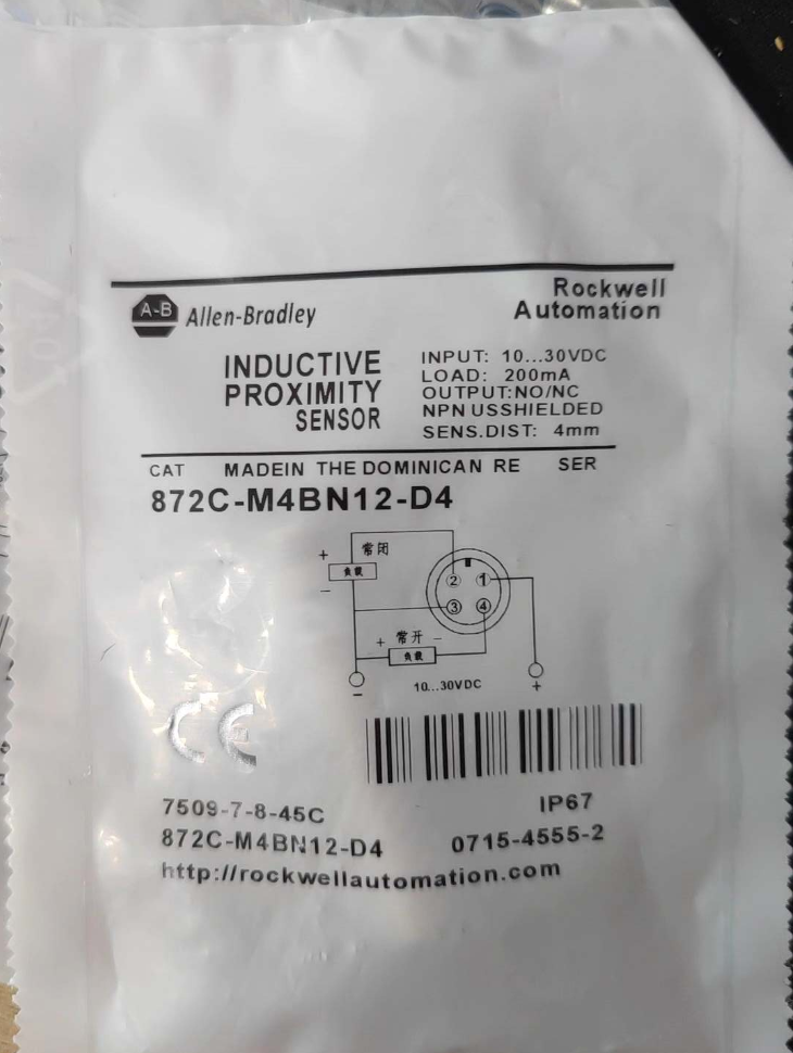
Full Model Number: 871TS-M4BN12-D4 (abbreviated as M4BN12-D4)
Serie: 871TS Food-Grade Stainless Steel Inductive Senzor de proximitate
Tip: Shielded DC 4-Wire Complementary Output Proximity Switch
Starea ciclului de viață: Activ (In Production); 1-year factory warranty; Made in Italy
- Defalcarea codului de model (M4BN12-D4)
- M4: Nominal sensing distance of 4 mm, extended detection range
- B: Shielded flush mount design (can be fully embedded into metal mounting brackets without lateral magnetic leakage interference)
- N: NPN sinking output
- 12: M12 cylindrical thread outer diameter
- D4: 4-pin straight M12 micro quick-disconnect connector (Micro QD DC)
- Specificații electrice de bază
| Parametru | Caietul de sarcini |
| Tensiune de alimentare | 10…30 VDC |
| Tip ieșire | 4-sârmă, NPN, complementary simultaneous NO (Deschis normal) + NC (În mod normal închis) |
| Single Channel Load Current | ≤200 mA |
| Frecvența de comutare | 2 kHz |
| Residual Ripple | ≤10% |
| Protectie inversa polaritatii | Încorporat |
- Mecanic & Specificații de mediu
- Main Body
Outer Thread: M12×1
Material: Monolithic potting with 316L stainless steel housing (food hygiene grade, resistant to acid & alkaline washdowns)
Distanța de Sentire: Evaluat 4 mm (shielded design, no range attenuation after installation)
Stil de montare: Montaj încastrat ecranat
- Ingress Protection Ratings
IP67, IP68, IP69K (Suitable for high-pressure hot water jet cleaning)
- Interval de temperatură
Funcționează: -25℃ ~ +85℃
Depozitare: -40℃ ~ +85℃
- Certificari: CE, cULus, UKCA, RCM, KC, Conform RoHS
- Atribuire PIN (M12 4-Pin Male Connector)
1: Maro → DC24V pozitiv
2: Black → NO (Deschis normal) Ieșire
3: Blue → 0V GND
4: White → NC (În mod normal închis) Ieșire
- Series Distinction (871TS vs 872C-M4BN12-D4)
871TS-M4BN12-D4 (This Model): 316L stainless steel housing, IP69K rated, dedicated for food & băutură, pharmaceutical and washdown equipment
872C-M4BN12-D4: Carcasă din alamă placată cu nichel, for general industrial applications, not resistant to corrosive cleaning chemicals
- Scenarii tipice de aplicare
- Mâncare & beverage filling, sterilization and washdown lines (316L stainless steel withstands cleaning agents)
- Pharmaceutical equipment, cleanroom production
- Metal workpiece presence detection for packaging machinery
- Metal position limit counting on automated machine tools
- Cross-Replacement Selection Reference
PNP sourcing equivalent with identical output logic: 871TS-M4BP12-D4
Straight cable version without connector: 871TS-M4BN12
Short or extended body variants: Refer to the full 871TS series selection handbook
Complete Installation Procedures for Rockwell 871TS-M4BN12-D4 (M12 Shielded Flush-Mount Food-Grade Proximity Switch)
- Pregătirea înainte de instalare (Key Points for Food/Washdown Environments)
1.1 Lista de instrumente
14 mm open-end / box wrench (for tightening M12 hex lock nuts)
Cheie dinamometrică (0.5~2.0 N·m range)
Lint-free cloth, alcool izopropilic (for cleaning sensing face and threaded sealing surfaces)
M12 4-core straight cable (Matching part number: 871A-TS4-DM1)
Neutral food-grade lubricant (prevents thread seizing; strong acid lubricants prohibited)
24 Alimentare VDC, multimetrul, PLC digital input module (Tip de scufundare NPN)
1.2 Inspecția produsului
- Verificarea modelului: 871TS-M4BN12-D4, Filet M12×1, shielded flush mount, NPN 4-wire NO+NC, M12 straight 4-pin connector, 316L oțel inoxidabil, IP68/IP69K rated
- Inspecție vizuală: No scratches on sensing face, no dents on housing, intact sealing O-ring on rear connector, no water-induced whitening discoloration
- Accessory Check: Dual M12 lock nuts, şaibe plate, garnituri de etanșare (mandatory for IP69K washdown)
1.3 Condiție de funcționare & Mounting Hole Requirements (Core Features of B-Type Shielded Flush Mount)
Mounting Hole: Φ12.1±0.1 mm through metal hole; full metal mounting bracket is mandatory
Flush Mount Rule: The entire sensing face can be sunk fully inside the metal hole without lateral metal interference. Unshielded sensors cannot be embedded, while this B-type shielded unit supports full flush mounting
Effective Detection Gap: Evaluat 4 mm; reserve 2.5~3.2 mm during actual installation (70%~80% of nominal distance to avoid false triggering caused by vibration and temperature drift)
Target Material: Standard mild steel with thickness ≥1 mm; aluminum/copper targets reduce sensing range by 20%~40%, requiring reduced gap
Interference Clearance: Maintain ≥150 mm distance from inverters and servo power cables; minimum spacing of ≥24 mm between identical sensors (twice the M12 outer diameter)
- Step-by-Step Mechanical Installation (Critical for IP69K Sealing Performance)
Pas 1: Clean Mounting Hole and Sensor Threads
- Remove burrs, metal filings and oil stains inside the metal mounting hole, blow thoroughly with compressed air
- Wipe the 316L stainless steel sensor threads and sealing end face with isopropyl alcohol until fully dry and oil-free
- Apply a thin layer of food-grade neutral lubricant on threads; do NOT coat the front sensing face or sealing O-ring (grease will adsorb metal powder and shorten detection range)
Pas 2: Feed Sensor and Assemble Washers (Assembly Sequence Cannot Be Reversed)
Assembly Order (From Probe to Rear Connector):
- Sealing flat washer (fits tightly against equipment metal panel)
- First lock nut (outer fixed nut)
- Equipment mounting panel
- Second lock nut (inner limiting nut)
Operation Instructions:
Feed the sensor probe outward from the inner side of the equipment, with sensing face facing the target workpiece
Thread both front and rear lock nuts loosely without tightening, reserving adjustable travel
Pas 3: Calibrate Sensing Distance and Orientation
- Slide the sensor to adjust probe protrusion depth, leaving a 2.5~3.2 mm gap between stationary metal workpiece and sensing face
- Rotate the rear M12 connector to the optimal cable routing angle (360° rotatable without damaging internal sealing)
- Confirm no twisting or tensile stress on cables, no sharp bending dead angles on the connector
Pas 4: Torque Tightening (Core Step to Prevent Water Intrusion and Thread Rupture)
- Tighten the inner limiting nut first, then fasten the outer fixing nut
- Standard tightening torque: 1.0~1,2 N·m
De mai jos 0.8 N·m: Poor sealing, water ingress during high-pressure washdown, IP69K protection fails
Mai sus 1.5 N·m: Stripped 316L threads, cracked internal potting, permanent sensor damage
- For high-vibration production lines (ștampilarea, vibratory conveyors): Apply a small amount of removable Loctite 243 thread locker on threads; high-strength anaerobic adhesives are strictly forbidden
Pas 5: Mechanical Recheck
- Pull the sensor gently with both hands to confirm no displacement or rotation
- Ensure the sensing face is not covered by metal nuts or accumulated metal shavings
- No tensile load on the rear M12 connector; cables hang naturally or run inside cable conduits
- Electrical Wiring Installation (4-Pin Straight NPN 4-Wire Complementary Output)
3.1 Definiția PIN (M12 Male Straight 4-Pin Connector)
| PIN nr. | Culoarea firului | Funcţie | Observații |
| 1 | Maro | DC24V pozitiv | Alimentare pozitivă, protected by 1A fuse |
| 2 | Negru | NPN NO Output | Conducts when workpiece approaches (pulls load to 0V) |
| 3 | Albastru | 0V GND | Putere negativă, common ground reference |
| 4 | Alb | NPN NC Output | Conducts without workpiece, cuts off when target approaches |
3.2 Specificații de cablare (NPN Sinking Circuit)
- PLC Input Module: Connect signal wires (Negru/Alb) to PLC input terminals, link module COM common terminal to 24V+
- Load Current Limit: Single channel ≤200 mA; cannot drive solenoid valves directly, use intermediate relays for signal transfer
- Selectarea cablului: Matching M12 4-core shielded cable with 0.34~0.5 mm² conductor cross-section; separate power cables and sensor cables in different trunking with ≥100 mm clearance
- Shielding Treatment: Ground cable shield at cabinet end only, leave sensor-side shield floating to eliminate ground loop interference
3.3 Connector Waterproof Assembly (Mandatory for IP69K High-Pressure Washdown)
- Ensure male and female connector O-rings are intact and free of debris
- Hand-tighten connectors until mating surfaces fit flush, then rotate an extra 1/4 turn by hand; do not use wrenches to apply excessive torque on connectors
- Reserve cable bending allowance; avoid direct jet wash toward connector gaps
- Power-On Commissioning Procedures
4.1 Pre-Power Inspection
- Use multimeter to verify no short circuit between brown and blue wires, no continuity between signal wires and power lines
- Confirm stable 24 Alimentare VDC (10~30 VDC, clipoci <10%)
- Complete load wiring; powering on without load is prohibited (output transistors may break down easily)
4.2 Power-On Test
- Apply 24 Alimentare VDC; green power LED on sensor rear stays steadily illuminated
- Move metal workpiece close to sensing face (2.5~3.2 mm):
Black NO wire conducts, yellow output LED lights up
White NC wire opens, yellow LED extinguishes
- Pull workpiece away (>5 mm): NO circuit opens, NC circuit conducts, yellow LED turns off
- Repeat test 10 times consecutively; no missed detection, flickering or false triggering allowed
4.3 Distance Calibration
Declanșări false frecvente: Increase gap between workpiece and probe to 3.2 mm
Missed detection: Reduce gap to 2.5 mm and clean metal debris on probe surface
Interferențe electromagnetice severe: Replace shielded cable and increase separation distance from power cables
- Special Installation Notes for Food Washdown Environments (Core Application Scenario of This Model)
- Do not blast sensor threads and connector gaps directly with 80℃ high-pressure hot water; adjust jet angle to deviate ≥30° from sealing surfaces
- Only neutral cleaners and warm water are permitted for cleaning; prolonged soaking in hydrochloric acid, caustic soda, acetone or alcohol is prohibited
- Inspect nut torque and connector sealing O-rings monthly; replace gaskets/O-rings immediately upon whitening or aging
- Select 316L stainless steel mounting brackets to prevent rust debris from adhering to the sensing face
- Installation Forbidden Operations (Liniile roșii)
- Never tighten lock nuts with torque exceeding 1.5 N·m; this will damage the monolithic potting structure
- Do not grind or cut the stainless steel housing and sensing face of the sensor
- Do not embed the sensor into non-metallic holes (shielding magnetic field fails, sensing distance drastically attenuates)
- Avoid sharp bending, extrusion or long-term immersion of cables in cleaning fluid
- Reverse connection of 24V positive and negative poles is prohibited (built-in reverse protection exists, yet long-term reverse polarity shortens service life)
- Multiple sensors cannot be wired in series (voltage drop causes detection failure)
- Quick Post-Installation Troubleshooting Matrix
| Simptom de eroare | Cauza de bază | Pași de rezoluție |
| Green power LED does not light | Short circuit between brown & fire albastre / Loss of supply power | Tai puterea, inspect cables and replace fuse |
| No signal when workpiece approaches | Excessive detection gap / Metal shavings covering sensing face | Clean probe surface and reduce mounting gap |
| Signal flickers continuously | Loose mounting due to vibration / Interference from power cables | Retighten nuts and separate signal & cabluri de alimentare |
| Intermittent failure after washdown | Damaged connector O-ring / Cuplu de strângere insuficient | Replace sealing gaskets and retighten to standard torque |
| Output circuit burnt without load | Power applied without connected load | Add relay or indicator light as load component |





NH42-63-318x560.png "Comutatoare de transfer automat de tip PC CHINT (ATS)NH42-63/4SZ")



