 Contactor,întrerupător de circuit,senzor,Codificator,PLC,Convertor

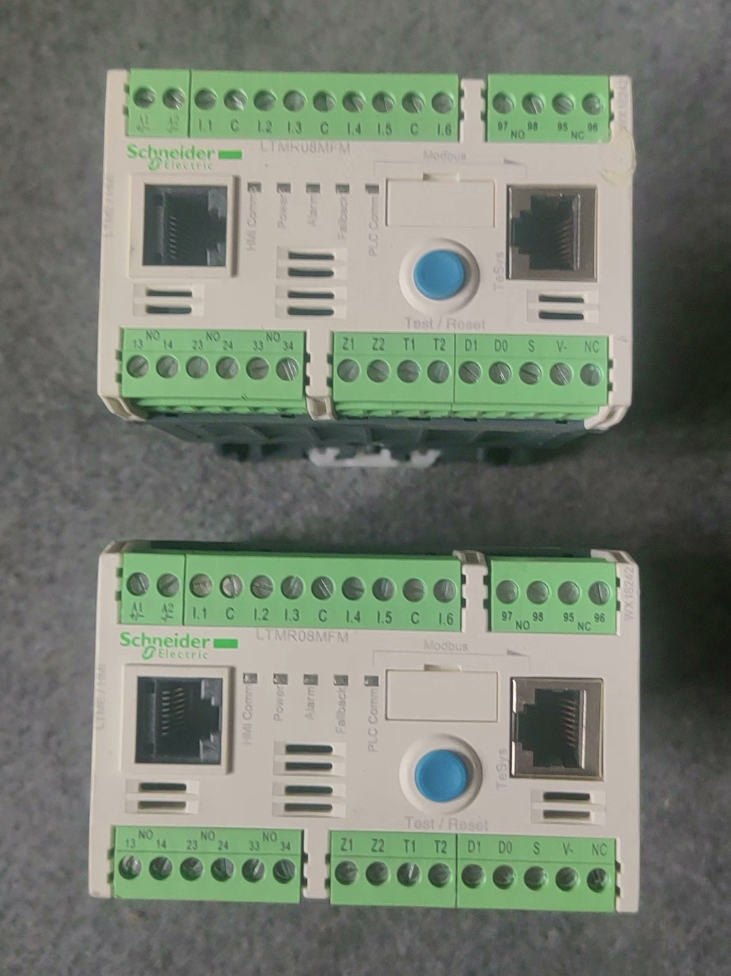

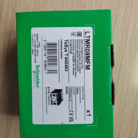
Schneider TeSys-T (Seria LTMR) Controler de management al motoarelor — Scenarii de aplicație
TeSys-T este o protecție inteligentă a motorului & unitate de monitorizare. Valorile fundamentale: protecţie completă a motorului + Control logic I/O + Bus Modbus RTU pentru date motor & încărcarea jurnalului de erori. Vizează motoarele asincrone trifazate care necesită protecție fină, monitorizare de la distanță și întreținere predictivă. Este necesar un contactor extern pentru pornirea-oprirea motorului.
Stare produs: Învechit planificat, Data de sfârșit al vieții: sept 30, 2026
Serie: Unitate inteligentă de management al motoarelor TeSys‑T, Comunicare Modbus-RS485, 0.4Protecție circuit motor ‑8A & monitorizare
- Defalcarea codului de model
| Domeniu | Cod | Descriere |
| LTM | LTM | Seria de sisteme de management al motoarelor TeSys-T |
| R | R | Corpul controlerului |
| 8 | 8 | Interval de măsurare a curentului nominal 0,4-8A |
| M | M | Comunicare: Modbus RTU (RS485) |
| F | F | Alimentare de control: 100-240V AC |
| M | M | Versiunea terminalului M (terminale standard, 6DIN / 3Ieșiri releu DO) |
- Principalul electric & Specificații hardware
| Articol | Valoare |
| Domeniul de măsurare a curentului motorului | 0.4 … 8A |
| Controlul tensiunii de alimentare | 100-240V AC; toleranta de functionare: 93.5~264V AC, 50/60 Hz |
| Intrări logice (DIN) | 6Intrări logice de tip AC pe canal; 0-40V = stare OPRIT, 79‑264V = stare ON |
| Ieșiri releu (DO) | 3NU + 1releu de eroare NO+1NC; evaluarea contactului: AC250V/5A; DC30V/5A |
| Interfață de comunicare | Modbus-RTU RS485; dublu RJ45 + portul blocului terminal; baud rate:1.2~19,2 kbit/s; interval de adrese:1‑247 |
| Dimensiunea de ansamblu (H×L×D) | 61 × 91 ×122,5 mm; greutate:0.53 kg; Montare pe șină DIN |
| Temperatura ambiantă de funcționare | -20 ℃ … +60℃; temperatura de depozitare:-40℃~+85℃; condens interzis |
| Tensiunea nominală de izolație Ui | 690 V; gradul de poluare3, categoria de supratensiune III |
| Cuplul cablajului | 0.5-0,6 N·m; ecartamentul firului:0.2-2,5 mm² solid / cablu flexibil |
III. Funcții de protecție încorporate
Protecție de lungă durată la suprasarcină termică, protecție cu rotor blocat, pierdere de fază, dezechilibru de fază, inversare de fază, protecție împotriva scurgerii la pământ
Date inregistrabile: evenimente de eroare, curent de pornire, contor de ore de functionare, contextul călătoriei, capacitatea termică reziduală; pre-alarma suportată
Expansiune: cu modul de extensie LTME pentru măsurarea tensiunii, factor de putere și protecție la variația sarcinii
- Principiul de funcționare aprofundat
- Achizitie curenta: Trifazat încorporat transformatoarele de curent măsoară motorul curent RMS adevărat; detecție integrată a curentului de defecțiune la pământ.
- Model termic: Algoritmul de memorie termică a motorului încorporat simulează creșterea temperaturii motorului pentru protecție la suprasarcină; întârziere de răcire aplicată după declanșare.
- Logica I/O: 6 DI primesc pornire/oprire externă / comenzi locale-la distanță; 3 ieșirile releului acţionează bobinele contactorului; releul de eroare oferă semnal de alarmă.
- Autobuz Modbus: Încărcați curent, starea termică, coduri de eroare, starea de funcționare; primiți comenzi de pornire-oprire de la distanță și de modificare a parametrilor.
- Buton local albastru TEST/RESET: resetare manuală a erorilor & test local; indicatoare LED de pe panoul frontal (PUTERE / RUN / ALARMA / VINEA).
Nota: Această unitate efectuează doar protecție & control logic. Contactorul circuitului principal trebuie să fie cablat extern pentru a construi un circuit complet de pornire a motorului.
- Definiții ale terminalelor cheie (Rezumat)
A1/A2: Alimentarea controlerului, 100-240VAC
C1-C6: 6 canale de intrare logice (DIN)
21-24, 31-34: 3 FĂRĂ ieșiri cu releu (pentru acţionarea contactorului)
95‑96‑97: Releu de eroare, 1NU+1NC
Modbus: RS485 cu două porturi (RJ45 + bloc terminal), acceptă rețele în lanț în margaretă
- Upgrade & Soluție de înlocuire (Seria oficială de nouă generație TeSys-Tera)
TeSys-Tera adoptă arhitectură separată: corpul controlerului + senzori externi CT. Înlocuirea directă a hardware-ului pin-la-pin față de vechiul LTMR nu este fezabilă; Este necesară modificarea cablajului de detectare a curentului.
| Sistem | Unitatea principală | Senzor de curent | Interval de curent aplicabil |
| Schema 1 | LTMTMFM (Modbus, 100-240VAC/DC) | LTMTCTV3UT | 0.3-3A |
| Schema 2 | LTMTMFM (Modbus, 100-240VAC/DC) | LTMTCTV25UT | 2.5-25A |
⚠ Riscurile de actualizare:
- LTMR vechi integrează CT intern; noul Tera folosește CT extern, este necesară modificarea cablajului cabinetului.
- Maparea registrului Modbus & parametrii nu sunt pe deplin compatibili; Modificarea programului PLC & punerea în funcțiune sunt obligatorii.
- Dispunerea terminalelor I/O este complet diferită; cablurile secundare din interiorul dulapului de comandă trebuie reluate.
VII. Scenarii tipice de aplicare
Motoare asincrone trifazate, cum ar fi pompele, fani, compresoare și transportoare; tratarea apei, metalurgie, petrol-gaz, chimic, industriile cimentului; bucle critice ale motorului care necesită acces la magistrala bazată pe PLC pentru starea protecției motorului și citirea jurnalului de defecțiuni.
VIII. Note de selecție & Condiții limită
- Curent maxim de măsurare 8A; nu se aplică pentru motoarele cu curent nominal mai mare de 8A.
- DI-urile sunt intrări de tensiune AC, nu intrări cu contact uscat; pentru închiderea contactului este necesară tensiunea de alimentare externă.
- Frecvența maximă de comutare a ieșirii releului: 2 Hz; nepotrivit pentru aplicații de ciclism de înaltă frecvență.
- Protecția la nivelul dulapului este necesară pentru mediile predispuse la condens sau corozive.
- Sfârșitul vieții planificat: 30-sept-2026; proiectele noi vor adopta TeSys-Tera în mod preferențial.
- Echipamente industriale de proces general (Cele mai comune)
- Ventilator & Circuite pompe
Pompe de circulație, pompe de racire, pompe de canalizare, pompe de apă de completare, ventilatoare de evacuare a fumului, ventilatoare de alimentare-retur, ventilatoare pentru turnul de răcire.
Valori: suprasarcina, rotor blocat, pierdere de fază & protectie la pamant; încărcați curentul de rulare, starea defecțiunii și timpul de rulare; protecţie la subsarcină pentru prevenirea funcţionării în uscat al pompei.
Industrii: HVAC, tratarea apelor uzate, lucrări de apă, clădirea europarlamentarului.
- Transportoare, alimentatoare cu bandă & alimentatoare cu șurub
Transportoare cu bandă, transportoare cu raclete, alimentatoare cu șurub, ascensoare cu cupe.
Valori: deplasare rapidă la blocaj mecanic; dezechilibru de fază & protectie la pamant; istoricul defecțiunilor pentru analiza incidentelor de blocaj; suport logic de interblocare.
Industrii: minerit, materiale de constructii, depozitarea cerealelor, manipulare logistică, prelucrare chimică.
- Compresoare & unități frigorifice
Compresoare de aer cu șurub, compresoare frigorifice, compresoare de proces.
Valori: previne blocarea rotorului / suprasarcină cauzată de lichid-slugging; protecția înfășurării modelului termic; încărcați starea motorului pe PLC / SCADA prin fieldbus.
- Tratarea apei & Industria Municipală (Implementare TeSys-T de mare volum)
Ridicați pompele, pompe de retur, motoare agitatoare pentru dozare chimică, suflante de aerare, ecrane bar, răzuitoare.
Caracteristicile site-ului: cantitate mare de motoare distribuite geografic; monitorizarea de la distanță a curentului & defecțiuni pentru a reduce inspecția la fața locului; incidență mare a pierderii de fază & defecțiuni la pământ.
Arhitectură tipică: Rețea multi-drop Modbus-RTU cu PLC, agregarea datelor de protecție a motorului către gazda SCADA.
- Chimic & Industria farmaceutică
Agitatoare de reactoare, pompe de circulatie, pompe de dozare, pompe de transfer de material, centrifuge.
Valori:
- Protecție împotriva scurgerii la pământ care atenuează daunele motorului cauzate de scurgerile din mediul de proces.
- Jurnal complet de erori pentru trasabilitatea procesului și conformitatea cu GMP.
- Protecție împotriva inversării fazelor pentru a preveni rotația inversă după schimbarea fazei de întreținere.
Nota: Corpul controlerului nu poate fi instalat direct în zone explozive periculoase; carcase rezistente la explozie / sunt necesari contactori.
- Metalurgie, Ciment & Materiale de constructii
Ventilatoare pentru îndepărtarea prafului, ventilatoare de racire, distribuitoare de actuatoare, descărcarea unităților, motoare mici de masă cu role.
Condiții de funcționare: încărcare grea de șoc, praf mare; frecvent blocat-rotor & evenimente de pierdere de fază; suprasarcină termică combinată & deplasarea rapidă cu rotorul blocat protejează înfășurările motorului.
- Acționări auxiliare ale centralei electrice
Motoare auxiliare mici: ventilatoare de racire, pompe de ulei lubrifiant, pompe de apă cu etanșare.
Valori: echipamente auxiliare critice; pre-alarma & înregistrarea instantanee a erorilor pentru analiza cauzei principale după incidente.
- Logistică-ambalare & Mașini pentru materiale plastice
Benzi transportoare, agitatori, alimentatoare, antrenări auxiliare pentru extrudere mici.
Avantaje: local / selectarea modului de la distanță prin DI; Comandarea bobinei contactor prin DO elimină numeroase relee intermediare.
✅ Criterii de selecție pentru TeSys‑T
Alegeți LTMR dacă se aplică oricare dintre condițiile de mai jos:
- Este necesară comunicarea Fieldbus: curent de citire, procentul de capacitate termică, orele de funcționare, coduri de eroare și instantanee de eroare.
- Motoare valoroase care necesită protecție completă: suprasarcină termică, rotor blocat, pierdere de fază, dezechilibru de fază, inversare de fază, defect la pământ, subîncărcare.
- Mod de control dublu la distanță local plus logică complexă de interblocare; reduce numărul de relee intermediare.
- Cerință la fața locului pentru înregistrarea erorilor pentru depanarea post-eveniment.
- Rețea de monitorizare centralizată cu mai multe motoare conectată la PLC / SCADA.
❌ Scenarii de aplicații nepotrivite
- Este necesară doar o protecție simplă prin releu termic, fără comunicare sau înregistrarea erorilor: selectați în schimb releele termice de suprasarcină LRD ieftine.
- Curentul la sarcină maximă a motorului depășește cu mult domeniul CT încorporat (max integrat-CT LTMR:100 O). Utilizați TeSys-Tera de nouă generație cu CT extern pentru motoare cu curent mai mare.
- Ciclism cu motor de înaltă frecvență: releu DO frecvență max de comutare 2Hz; uzura contactului se va accelera.
- Zone periculoase cu siguranță intrinsecă: corpul controlerului nu poate fi montat în zonele periculoase.
- Protecția motorului monofazat: TeSys-T vizează motoarele cu inducție trifazate.
📌 Rezumatul generației vechi versus nouă
Moştenire: Seria LTMR (de ex. LTMR08MFM), EOL planificat 30-09-2026, transformatoare de curent încorporate.
Nou: TeSys-Tera (Seria LTMT), arhitectură externă-CT, acoperire curentă mai largă; preferat pentru ingineria noilor proiecte.
Principiul de protecție la suprasarcină termică al Schneider TeSys-T (LTMR)
TeSys-T nu se bazează pe deformarea fizică a benzilor bimetalice ca releele termice convenționale. Implementează protecție la suprasarcină termică prin modelul termic electronic (algoritmul de memorie termică a motorului virtual) + eșantionarea curentului trifazat cu RMS adevărat.
- Etapa de achiziție hardware
- Transformatoarele de curent trifazate încorporate eșantionează curentul RMS real al statorului (nu simple valori de vârf).
- Circuit integrat de detectare a curentului de defecțiune la pământ.
- Semnalele de curent analogic sunt digitizate de MCU pentru reîmprospătarea periodică a curentului de sarcină.
Pentru LTMR08MFM: domeniul de măsurare CT intern:0.4‑8A pentru măsurarea curentului direct în bucla statorului.
- Miez: Model termic cu motor virtual (Memorie termică)
Controlerul rulează un model matematic care simulează acumularea de căldură prin bobinajul motorului și disiparea căldurii:
theta_{virtual} \propto \int(I^2 \cdot t)dt
Acumulare de căldură: Procentul de capacitate termică crește atunci când curentul de funcționare depășește curentul nominal al motorului.
Disiparea căldurii: Procentul de capacitate termică scade în timpul opririi sau a funcționării cu sarcină ușoară, simulând răcirea naturală a motorului.
Doi parametri cheie configurabili determină comportamentul modelului:
- Curentul nominal al motorului Ir: setat în conformitate cu curentul de sarcină maximă de pe plăcuța de identificare a motorului.
- Clasa de călătorie (5/10/15/20/30), definește caracteristicile de declanșare în timp invers.
📌 Procent de capacitate termică: variabilă internă 0-100%; declanșarea supraîncărcării se declanșează la 100%. Această valoare poate fi citită prin intermediul registrului Modbus.
Definiție pentru clasa de călătorie
| Clasa de călătorie | Timp de călătorie @7,2×Ir | Aplicație tipică a motorului |
| Clasa 5 | 4-5s | Motoare cu pornire rapidă |
| Clasa 10 | 6-10s | Motoare cu inducție trifazate standard de uz general (cel mai folosit) |
| Clasa 15 | 9-15s | Aplicații de pornire grele |
| Clasa 20 | 12-20 de ani | Motoare cu pornire grea cu inerție mare |
| Clasa 30 | 18-30 de ani | Sarcini cu inerție mare cu timp de pornire lung (de ex. ventilatoare mari) |
- Manevrarea supraîncărcării pentru două condiții de funcționare tipice
① Suprasarcină de funcționare continuă (supracurent persistent)
Motorul funcționează continuu cu I>Ir; capacitatea termică virtuală se acumulează până la atingerea 100%. Controlerul emite comanda de declanșare, dezactivează ieșirile releului contactor-bobină și oprește motorul. Cod de eroare de supraîncărcare plus instantaneu de eroare (3-curent de fază & capacitatea termică la momentul deplasării) sunt stocate.
② Suprasarcină în timpul pornirii motorului (curent de pornire de amplitudine mare)
Clasa de declanșare configurată permite un curent de pornire ridicat pe termen scurt, fără declanșări neplăcute; modelul termic scade căldura acumulată după finalizarea pornirii.
⚠ Caracteristică critică: Reținerea memoriei termice
După deplasarea la suprasarcină, Valoarea capacității termice virtuale nu se resetează imediat, chiar dacă sursa de alimentare a controlerului rămâne activă. Timpul de răcire simulat de model trebuie să treacă sau este necesară RESETARE manuală.
Caz practic: după declanșarea motorului de la suprasarcină, înfășurările rămân fierbinți. Resetare instantanee & repornirea riscă arderea motorului. Memoria termică previne repornirea prematură și imită comportamentul de răcire a motorului real.
- Funcția de pre-alarma (Avertizare timpurie de suprasarcină)
Prag configurabil de capacitate termică (de ex. 80%). Când capacitatea termică virtuală depășește pragul, prealarma de suprasarcină se activează fără declanșare. Semnalul de avertizare poate fi transmis prin releul DO sau Modbus pentru întreținere predictivă înainte de oprirea neplanificată.
- Comparaţie: Releu termic bimetalic convențional față de modelul termic electronic TeSys-T LTMR
| Articol | Releu termic bimetalic LRD tradițional | Protecție la suprasarcină cu model termic electronic TeSys-T LTMR |
| Principiul de protecție | Deformarea termică fizică a benzii bimetalice | Model termic virtual bazat pe software cu eșantionare de curent RMS |
| Caracteristica memoriei termice | Căldura dispare la pierderea puterii; fara retentie termica | Memoria termică poate fi păstrată la pierderea puterii (configurabil) |
| Influența temperaturii ambientale | Puternic, dependent de temperatură a cabinetului, abatere notabilă | Software de compensare a temperaturii; sensibilitate scăzută la temperatura mediului |
| Setarea clasei de călătorie | Fix (modelele limitate suportă ajustarea) | Clasa 5-30 configurabilă prin software |
| Disponibilitatea datelor | Nicio ieșire de stare | Capacitate termică citibilă de autobuz, instantanee de eroare, măsurători curente |
- Condiții la limită & Limitări
- Protecția la suprasarcină protejează acumularea termică a înfășurării motorului, nu cabluri de alimentare; întrerupător separat necesar pentru protecția conductorilor de cablu.
- Pierdere de fază / dezechilibrul de fază accelerează acumularea modelului termic și avansează pragul de declanșare.
- Rotorul blocat și defecțiunea la pământ sunt funcții de protecție independente, nu face parte din logica supraîncărcării.
- Reglați Clasa de deplasare dacă starea reală de răcire a motorului se abate de la modelul intern (de ex. motor răcit cu aer forțat).
- Modelul termic LTMR este proiectat pentru motoarele cu inducție standard trifazate. Reutilizarea directă pentru motoarele alimentate cu VFD sau cu scop special este invalidă; reglarea parametrilor este obligatorie.
- Logica de resetare a erorilor
- Resetare automată: activat pentru parametri; resetarea are loc numai după ce modelul termic se răcește la nivelul sigur al capacității termice.
- Resetare manuală: butonul local RESET de pe panoul frontal, Semnal de resetare a terminalului IN, sau comanda de resetare Modbus-bus.
Operare interzisa: reporniri forțate repetate înainte ca motorul să se răcească după declanșarea termică.
- Cod de eroare
Cod de declanșare prin suprasarcină termică: Olimpiada 1. Jurnalul de erori stochează marca temporală, curent trifazat și procent de capacitate termică, recuperabil prin Modbus.



NH42-63-318x560.png "Comutatoare de transfer automat de tip PC CHINT (ATS)NH42-63/4SZ")



