 Контактор,автоматический выключатель,датчик,Кодер,ПЛК,Конвертер

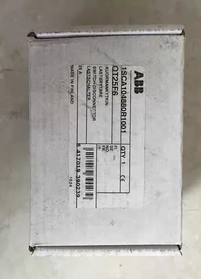

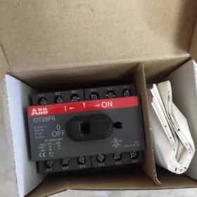
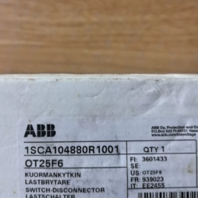
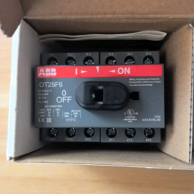
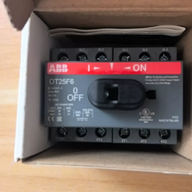
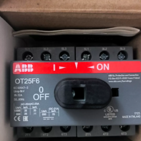
Заказ №.: 1SCA104880R1001, Сделано в Финляндии. Ручка и вал НЕ входят в комплект.; аксессуары для управления заказываются отдельно.
Пояснение кода модели
ОТ: Выключатель-разъединитель нагрузки серии ОТ
25: Номинальный рабочий ток 25А
Ф: С фронтальным управлением; совместим с монтажом на базовые винты и монтажом на DIN-рейку
6: 6-столб (6П)
Основные электрические характеристики
| Элемент | Параметр |
| Количество полюсов | 6П |
| Номинальный рабочий ток Ie (АС‑21А) | 25 А |
| Условный тепловой ток Ith | 32 А |
| Номинальное напряжение изоляции Ui | 750 В переменного тока |
| Импульсное выдерживаемое напряжение Uimp | 8 кВ |
| Терминалы | Защищенные клеммы; медный проводник 0,75‑10 мм² |
| Механическая выносливость | 20 000 операций |
| Степень защиты | Фронтальная IP20 |
| Устойчивость к короткому замыканию (с предохранителем 25А) | 50 кА |
| Код ТН ВЭД | 85365080 |
Механические размеры
Ширина×Высота×Глубина: 70 ×68×68мм. Входящие/исходящие кабели могут быть проложены сверху вниз или снизу вверх..
Монтаж & Аксессуары
- Варианты монтажа: Крепление на рейку DIN35 + винтовое крепление основания
- ⚠️Рукоятка и вал управления не входят в комплект базового блока.. Ручки в сборе (например. Серия ОХС) для работы необходимо приобретать отдельно; поддерживается внешнее управление на двери.
- Вспомогательные контактные блоки (Серия ОА1Г) может быть установлен в качестве дополнительного оборудования.
- Запирается навесным замком в положении ВЫКЛ для безопасной изоляции при обслуживании..
Типичные применения
Многоконтурная изоляция переменного/постоянного тока для фотоэлектрических объединительных коробок, системы хранения энергии и ИБП
Сервисный разъединитель внутри шкафов управления преобразователями частоты и устройствами плавного пуска
6-конфигурация полюсов: 3-фаза + 3-Изоляция цепи постоянного тока, сценарии двойной трехфазной изоляции
Эквивалент & Ссылки на замену
Оригинал АББ: Только базовый блок OT25F6; Не путать с OT25FT6. (FT = тип крепления к двери)
Внутренняя альтернативная ссылка: ЧИНТ НХ2-25-6П, Разъединитель Деликси 6П-25А (перед заменой проверьте монтажные размеры и емкость клемм.)
Распространенные ловушки
- OT25F6 поставляется только в виде базового блока.. Ручка не предусмотрена; прямое ручное управление невозможно. Ручки часто опускаются при заказе проекта..
- Не смешивайте Ф (база / Крепление на DIN-рейку) и ФТ (дверное крепление) варианты. Они механически невзаимозаменяемы..
- Для работы с нагрузкой двигателя в соответствии с категорией использования AC-23A требуется снижение номинальных значений тока..
Инструкция по эксплуатации ABB OT25F6 (OT-серия) Выключатель-разъединитель
⚠️Важное примечание.: Базовый блок OT25F6 оснащен только квадратным отверстием приводного вала.. Никакая ручка или вал не установлены на заводе.. ОХС / Рукоятки OHB должны быть установлены перед началом работы.. Никогда не поворачивайте отверстие оголенного вала напрямую..
Два типа ручек
- Внутренняя прямая ручка шкафа (ОХС): Устанавливается на передней стороне корпуса переключателя для работы внутри корпуса..
- Внешняя ручка для установки на дверь (ОНБ / ОХИС): Используется с удлиненным квадратным валом; ручка, прикрепленная к поверхности двери шкафа. Оснащен дверным замком: Дверь шкафа не открывается, когда переключатель включен. (состояние возбуждения). Дверь можно открыть только при выключенном выключателе..
Стандартное ручное закрытие / Открытая операция
Закрывать (НА, включить цепь питания): Поверните ручку по часовой стрелке до характерного щелчка, который заблокирует механизм.. Совместите маркер ручки с I / Положение ВКЛ для обеспечения полного замыкания контактов.
Открыть (ВЫКЛЮЧЕННЫЙ, изолировать цепь): Поверните ручку против часовой стрелки до характерного щелчка, который заблокирует механизм.. Совместите маркер ручки с 0 / Положение ВЫКЛ для создания безопасного изолирующего зазора.
✅Всегда поворачивайте в полностью заблокированное положение.. Промежуточные положения приводят к плохому контакту и перегреву..
СЕРДЦЕ (Блокировка-Тагоут) для технического обслуживания
Блокировка возможна только в положении ВЫКЛ. (блокировка в положении ВКЛ не поддерживается).
- Полностью поверните ручку в положение ВЫКЛ..
- Поднимите защелку замка на ручке.
- Установите навесные замки (Макс. 3 замки одновременно, навесные замки, поставляемые конечным пользователем). Ручка механически заблокирована от вращения для изоляции энергии во время технического обслуживания..
- Разблокировать: Снять замки, сбросить хасп, затем возобновите работу.
Вспомогательная контактная сигнализация (Дополнительный аксессуар OA1G)
С установленным блоком вспомогательных контактов:
Когда переключатель включается, изменение состояния вспомогательного контакта, подача сигнала обратной связи по положению на ПЛК или индикаторные лампы.
Вспомогательные контакты следуют за положением механического переключателя., независимо от наличия напряжения в сети.
Примечания по эксплуатационной безопасности
- Выключатели-разъединители OT могут коммутировать номинальную нагрузку в режиме AC-21A.. Снижение номинального тока для приложений с нагрузкой двигателя AC-23A.. Он не может отключать токи короткого замыкания.; предохранители или автоматические выключатели должны быть установлены на входе.
- Никогда не применяйте силу к заклинившей ручке.. Если ручка заедает, обесточить оборудование и исследовать механические препятствия.
- Для версий с дверной блокировкой: Невозможность открыть дверь при включенном состоянии является нормальной функцией безопасности.. Не открывайте дверь с силой. Всегда выключайте питание перед открытием шкафа для технического обслуживания..
- Это устройство обеспечивает только функцию изоляции. Всегда проверяйте отсутствие напряжения перед работами по техническому обслуживанию., даже если переключатель выключен.
- Кабельный вход / направление вывода кабеля можно изменить на противоположное (сверху вниз или снизу вверх) без изменения логики работы.
Общие эксплуатационные симптомы
| Симптом | Первопричина | Средство |
| Ручка не может вращаться | Замок не снят; напряжение дверной блокировки; помехи от посторонних предметов | Снять замок; подтвердить, что дверь полностью закрыта; обесточить и проверить механизм |
| Нет выходной мощности, когда ручка находится в положении ВКЛ. | Ручка не до конца сидит; незакрепленные клеммы | Плотно поверните до фиксации ВКЛ.; затяните кабельные наконечники |
| Дверь шкафа не закрывается | Неправильная длина удлиненного вала, вызывающая механические помехи. | Отрегулируйте глубину вставки удлиненного вала |
Распространенные неисправности & Troubleshooting for ABB OT-Series Switch-Disconnectors (including OT25F6)
Предупреждение о безопасности: All maintenance work must be performed with power disconnected and LOTO lockout applied. The OT-series base unit cannot be disassembled for repair. Replace complete unit if internal contacts or mechanism are damaged. Do not open the housing.
- Stiff / Jammed / Hard-to-rotate handle
| Неисправность Причина | Решение |
| Padlock engaged; cabinet door not fully closed (OHB external‑handle interlock) | Снять замок; fully close cabinet door before operating |
| Extended square‑shaft too long or too short, mechanical binding against enclosure | Adjust shaft length; maintain 2‑3 mm clearance; do not apply brute force |
| Dust or metallic debris infiltrating mechanism gaps | Обесточить, wipe clean with dry cloth; do not flush unit with liquid solvents |
| Internal mechanical wear or jamming | Do not force handle; заменить полный выключатель-разъединитель |
Частая ошибка: Никогда не поворачивайте оголенное квадратное отверстие вала на базовом блоке без установленной ручки.; внутренний механизм будет разрушен.
- Выход без нагрузки, потеря фазы или прерывистая проводимость при положении ручки в положении ВКЛ.
| Неисправность Причина | Решение |
| Ручка остановилась в промежуточном незаблокированном положении | Поворачивайте ручку до тех пор, пока не услышите щелчок и не совместите ее с маркером ВКЛ. |
| Ослабленные клеммные винты; неправильное обжатие проводника | Обесточить и снова затянуть клеммы.; предотвратить воздействие оголенной меди |
| Нет восходящего питания; перегорели предохранители на входе | Проверьте напряжение на входной стороне; проверить защитные устройства выше по потоку |
| Внутренняя эрозия главного контакта (перегрузка или переключение сильного тока) | Измерьте непрерывность на каждом полюсе. Замените весь блок, если на каком-либо полюсе имеется обрыв цепи.. |
- Перегрев корпуса переключателя / горячие терминалы / запах гари
| Неисправность Причина | Решение |
| Недостаточный момент затяжки клемм.; плохая обжимка | Затяните клеммы с указанным моментом затяжки.; используйте наконечники для гибких медных проводников |
| Постоянная перегрузка; неспособность снизить номинальные характеристики двигателя AC‑23A | Проверьте рабочий ток; установите предохранители / автоматический выключатель на входе в качестве защиты от короткого замыкания |
| Заниженное сечение кабеля | Выберите размер кабеля, соответствующий номинальному току |
| Сильная эрозия контактов и высокое сопротивление контактов. | Подтвердите перегрев посредством термического осмотра.; немедленно заменить весь блок |
- Выходная сторона остается под напряжением в положении ВЫКЛ. (потеря изоляции)
| Неисправность Причина | Решение |
| Рукоятка не полностью заблокирована в положении ВЫКЛ. | Поверните против часовой стрелки до упора в положение блокировки 0/ВЫКЛ. |
| Приварные закрытые подвижные контакты (перегрузка / воздействие короткого замыкания) | Немедленно обесточить; заменить полный выключатель-разъединитель; не продолжать обслуживание |
| паразитический / наведенное напряжение на нисходящей проводке (Не переключать неисправность) | Провести проверку живых/мертвых; следящий источник наведенного напряжения во внешних цепях |
- Неисправность блокировки двери (Ручка наружная дверная OHB)
| Симптом | Средство |
| Дверца шкафа может открываться, пока переключатель включен. (отказ блокировки) | Проверьте глубину вставки квадратного вала; проверьте правильность сборки аксессуаров; замените ручку в сборе, если оборудование повреждено |
| Невозможно перевести ручку в положение «ВКЛ» при закрытой двери. | Дверь не полностью заперта; отрегулируйте дверной зазор и глубину выдвинутой шахты |
- Отсутствует или обратный сигнал от установленных вспомогательных контактов OA1G.
| Неисправность Причина | Решение |
| Блок вспомогательных контактов не полностью зафиксирован на месте | Обесточить, снимите и установите на место блок вспомогательных контактов до фиксации |
| Неправильное подключение клемм вспомогательных контактов | Подтвердить НЕТ / Определение клеммы NC OA1G |
| Повреждены внутренние детали вспомогательных контактов. | Заменяйте только блок вспомогательных контактов.; главный коммутационный блок может оставаться в эксплуатации |
- Функция замка LOTO не работает; невозможно зафиксировать в положении ВЫКЛ.
| Неисправность Причина | Решение |
| Защелка навесного замка не полностью открыта | Полностью поднимите защелку перед установкой навесного замка. |
| Механическое повреждение защелки на ручке аксессуара | Заменить всю ручку в сборе |
- Ненормальная работа цепи постоянного тока (PV / приложения для хранения энергии)
Симптом: Сильное искрение во время операций открытия и закрытия.
Причина: Стандартный выключатель нагрузки переменного тока OT-F имеет ограниченную отключающую способность постоянного тока.. Для высоковольтных цепей постоянного тока, выберите специальные выключатели-разъединители постоянного тока OTDC. Не используйте стандартный OT25F6-6P для многократного отключения нагрузки постоянного тока.; произойдет эрозия контактов.
Рекомендации по текущему техническому обслуживанию выключателей-разъединителей серии ОТ
- Проводить визуальный осмотр каждые 6 месяцев.: Проверьте клеммы на предмет обесцвечивания / перегрев, проверить плавность работы ручки. Избегайте промежуточных рабочих положений.
- Не очищайте пластиковый корпус жидкостью или растворителями.; wipe dust with dry cloth only.
- Never disassemble switch housing. Replace complete unit for internal-contact or mechanism damage.
- Switch-disconnector cannot interrupt short-circuit faults. Fuses or circuit-breakers must be installed upstream.
Installation Notes for ABB OT-Series Switch-Disconnector (OT25F6)
Applicable to OT-F (железной дороги / base-mount) диапазон. All installation work shall be performed de-energized with voltage verification by qualified electricians. Handle and shaft are not supplied with base unit and must be ordered separately; this is the most-frequently-made error.
- Механический монтаж
- Способы монтажа
- Монтаж на рейку DIN35: Clip onto DIN rail and engage bottom latch fully to prevent vibration-induced detachment.
- Base-plate screw mounting: Use M4 screws; tighten diagonally. Do not over-stress housing by one-sided fastening.
- Ориентация монтажа: Вертикальный, horizontal or ceiling-mount (inverted) installation is permissible; performance remains unchanged.
- Дифференциация модели:
OTxxF: Устройство монтируется на DIN-рейку / опорная плита; совместим с ручкой OHS для внутреннего шкафа или ручкой OHB для внешнего монтажа.
ОТxxFT: Тип крепления к двери; блок крепится непосредственно к дверной панели шкафа. Механически невзаимозаменяем с OTxxF.
- Ручка для наружной установки на дверь (ОНБ / ОХИС) + удлиненная установка с квадратным валом
- Отрежьте удлиненный вал до точной длины. После сборки соблюдайте осевой зазор 2–3 мм.. Механизм блокировки вала избыточной длины; слишком короткий вал приводит к отключению привода и потере работоспособности.
- Проверьте работу блокировки двери после сборки.: Дверь не открывается при включении; дверь может открыться только в выключенном состоянии. Если блокировка не удалась, отрегулировать глубину вставки вала; никогда не взламывайте дверцу шкафа силой.
- После установки ручки, убедитесь, что маркеры положения на корпусе переключателя и рукоятке синхронизированы; нет позиционного смещения.
- Установка блока вспомогательных контактов (ОА1Г)
- Закрепите блок вспомогательных контактов в блоке сбоку до тех пор, пока не услышите уверенный щелчок фиксации.. Плохая посадка приводит к потере сигнала.
- Момент затяжки клемм вспомогательных контактов: 0.4-0.8 Н·м. Чрезмерный крутящий момент приведет к растрескиванию клеммного корпуса небольшого размера..
- Электрическая проводка (OT25F6)
- Нет обязательного направления ввода кабеля: Допускается проводка сверху-вниз или снизу-вверх..
- Спецификация проводника: 0.75-10 медные жилы мм². Используйте кабельные наконечники для многожильных гибких кабелей.; избегайте оголенных свободных прядей, которые могут вызвать короткое замыкание.
- Момент затяжки клемм: 2.2 Н·м. Используйте динамометрический ключ; не полагайтесь на ощупь. Низкий крутящий момент приводит к термическому перегреву.; переломы корпуса клеммы из-за чрезмерного крутящего момента.
- Установите защитные крышки клемм после подключения проводов, чтобы обеспечить защиту от прикосновения IP20..
- Выключатель-разъединитель не может отключить ток короткого замыкания. Предохранители или автоматические выключатели должны быть установлены на входе.
- Derate current for motor-load circuits under AC-23A utilization category.
III. Installation for DC Applications (PV / Energy-Storage)
- Standard OT-F AC-rated switch-disconnector has limited DC breaking performance. Для высоковольтных цепей постоянного тока, выберите специальные выключатели-разъединители постоянного тока OTDC. Do not repeatedly break DC load-current using OT25F-6P; arcing will erode contacts.
- Strictly observe positive-/negative-polarity wiring according to datasheet for DC-circuit connections.
- Условия окружающей среды
- Рабочая температура окружающей среды: -25 ℃ ~ +60 ℃. Current derating required above +40 ℃.
- Altitude rating: ≤ 2000 m. Derate insulation and current for installation altitude > 2000 m.
- Enclosure minimum protection class IP20. Избегайте сильной пыли, metallic particles, corrosive gas and condensation. Install enclosure heaters under condensing conditions to prevent creepage and insulation degradation.
- Do not expose unit to outdoor weather or rain.
- Проверки при вводе в эксплуатацию после установки
- Выполните несколько полных циклов включения-выключения.. Подтвердите четкое действие фиксации, плавное движение, нет промежуточных положений фиксации.
- Тест на блокировку LOTO: Убедитесь, что навесной замок можно установить в положении ВЫКЛ.; ручка блокируется от вращения.
- Тест вспомогательных контактов: Измерьте правильность сигнала во время включения. / Циклы переключения ВЫКЛ..
- Тест перед подачей питания: Измерение сопротивления изоляции между полюсами и землей.
- Ввод в эксплуатацию под напряжением: Периодически проверяйте клеммы на предмет аномального повышения температуры..
- Запрещенные действия
- ❌Не вращайте голый квадратный вал без установленной рукоятки.; произойдет повреждение внутреннего механизма.
- ❌Не разбирайте корпус переключателя.. Замените весь блок при повреждении внутреннего механизма.; ремонт в полевых условиях не допускается.
- ❌Не используйте выключатель-разъединитель в качестве устройства защиты от короткого замыкания вместо автоматического выключателя..
- ❌Не прилагайте усилий к заклинившей ручке.. Обесточить и выяснить механические причины..
- ❌Предотвратите попадание металлического мусора внутрь корпуса переключателя во время установки., что может привести к внутреннему короткому замыканию или заклиниванию.
VII. Сводка типичных ошибок установки
| Явление неисправности | Первопричина |
| Ручка не может повернуть | Слишком длинное крепление с удлиненным стержнем; дверь не полностью закрыта; замок не разблокирован |
| Нет выходной мощности в положении ВКЛ. | Ручка позиционного смещения, неполное участие; недостаточный крутящий момент на клеммах; отсоединение недостаточно вставленного карданного вала |
| Дверной замок не работает | Неправильная глубина установки вала.; неполная сборка аксессуаров |
| Перегрев терминала | Недостаточный момент затяжки; гибкие проводники без наконечников |





NH42-63-318x560.png "Автоматические переключатели резерва типа PC CHINT (АТС)НХ42-63/4СЗ")



