 Контактор,автоматический выключатель,солнечный инвертор,электрический счетчик,солнечные батареи

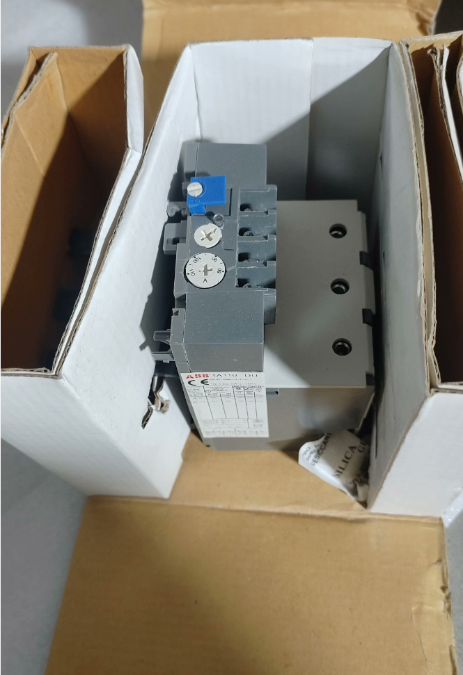

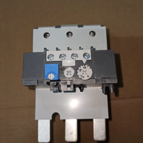
TA110DU110 — классический 3-полюсный вариант. тепловое реле перегрузки от АББ серия ТА, обеспечивает комплексную защиту трехфазных асинхронных двигателей с номинальным током 80–110 А.. Принятие принципа обратнозависимого срабатывания биметаллических полос, это реле стандартно поставляется с защитой от обрыва фазы и автоматической компенсацией температуры окружающей среды., с классом срабатывания 10А. Его можно подключить непосредственно к контакторам ABB серии A/AE/AF95~110 или установить независимо на DIN-рейках.. Оснащен переключаемыми режимами ручного/автоматического сброса и одним нормально открытым режимом. (НЕТ) плюс один нормально закрытый (Северная Каролина) контакт вспомогательного сигнала, он служит стандартным защитным компонентом для цепей управления промышленными двигателями.. Широко применяется для силовых нагрузок, таких как вентиляторы., водяные насосы, компрессоры и конвейерные линии, эффективно предотвращает перегорание обмоток двигателей, вызванное перегрузкой, блокировка ротора и потеря фазы.
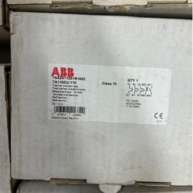
Полная модель: `ТА110ДУ110`
- ОБЛИЦОВКА: Общий код серии тепловых реле ABB, представляющее семейство электротепловых защитных реле
- 110: Номинальный ток корпуса, с указанием максимального номинального тока корпуса 110 А для этого продукта
- ИЗ: Код типа функции, означает стандартную спецификацию с 3-полюсной защитой, обнаружение потери фазы, компенсация температуры окружающей среды и непосредственный монтаж на контакторы
- 110: Верхний предел текущей настройки, соответствует регулируемому диапазону тока 80–110 А.
Основные технические характеристики
| Категория параметра | Параметр Элемент | Подробная спецификация |
| Характеристики главной цепи | Номинальное напряжение изоляции Ui | 690В и / 440В Вашингтоне |
| Номинальное рабочее напряжение UL/CSA | 600В и | |
| Регулируемый диапазон тока | Плавная регулировка от 80А до 110А. | |
| Класс поездки | Класс 10А (стандартный класс защиты двигателя) | |
| Количество полюсов | 3 столбы, полная 3-полюсная защита | |
| Защита от потери фазы | Стандартный встроенный; ускоряет срабатывание при трехфазном несимметрии | |
| Температурная компенсация | Поддерживается; Точность защиты остается неизменной при температуре окружающей среды -25℃ ~ +55℃. | |
| Вспомогательные контакты | Конфигурация контактов | 1 НЕТ + 1 Северная Каролина, электрически изолированный |
| Условный тепловой ток Ith | 5А | |
| Номинальная контактная способность | 250 В переменного тока, 3 А; 24 В постоянного тока 5 А | |
| Механический & Монтаж | Способ монтажа | Прямой монтаж на контакторы / независимая установка на DIN-рейку |
| Совместимые контакторы | Серия А95, А110, АЕ95, АЕ110, АФ95, АФ110 | |
| Способ подключения | Винтовые зажимы | |
| Общий вес | Приблизительно. 0.76кг | |
| Режим сброса | Переключаемый ручной/автоматический сброс; поддерживает расширение удаленного сброса | |
| Среда & Сертификаты | Рабочая температура окружающей среды | -25℃ ~ +55 ℃ |
| Температура хранения | -40℃ ~ +70 ℃ | |
| Степень защиты от проникновения | IP20 | |
| Сертификаты соответствия | CE, UL, CSA, CCC, ГЛ (Морская сертификация Germanischer Lloyd) | |
| Соответствующие стандарты | МЭК 60947-4-1, В 60947-4-1 |
Перекрестная ссылка на модели одной серии
- Полные характеристики рамы TA110DU
| Полная модель | Регулируемый диапазон тока | Совместимая мощность двигателя (380В) | Соответствующие контакторы |
| ТА110ДУ-65 | 50 ~65А | 30кВт | А95/АЕ95/АФ95 |
| ТА110ДУ-80 | 60 ~ 80А | 37кВт | А95/АЕ95/АФ95 |
| ТА110ДУ-90 | 66 ~ 90А | 45кВт | А110/АЕ110/АФ110 |
| ТА110ДУ-110 | 80 ~ 110А | 55кВт | А110/АЕ110/АФ110 |
- Сравнение соседних серий рамок
| Модель серии | Номинальный ток корпуса | Максимальный регулируемый ток | Применимые сценарии |
| ТА110ДУ | 110А | 110А | Середина & двигатели небольшой мощности (30~55кВт) |
| ТА200ДУ | 200А | 200А | Середина & двигатели большой мощности (75~110кВт) |
| ТА450ДУ | 450А | 450А | Мощные сверхмощные двигатели (132~250кВт) |
Типичные сценарии применения
- Стандартная схема защиты пускателя двигателя: В сочетании с контакторами ABB серии A/AF для создания электромагнитных пускателей., подключается последовательно к главной цепи трехфазных двигателей для реализации защиты от перегрузки двигателя., блокировка ротора и потеря фазы. Это стандартное решение для защиты силового оборудования общего назначения, включая вентиляторы., водяные насосы, воздушные компрессоры и шпиндели станков.
- Центры управления двигателями MCC: Служат стандартными устройствами защиты для цепей питания двигателей в выдвижных и стационарных шкафах., интегрирован с контакторами для реализации комплексного управления пуском и остановкой двигателя.
- Конвейер & Логистические сортировочные системы: Совместим с роликовыми двигателями и приводными двигателями сортировки., адаптация к частым стартам и колебаниям нагрузки на производственных линиях, и предотвращение старения и перегорания двигателя, вызванных длительной перегрузкой..
- Центральное кондиционирование & Холодильные установки: Защитите холодильное оборудование, такое как компрессоры и вентиляторы градирен., подходит для холодильной промышленности, характеризующейся резкими колебаниями нагрузки и сезонной работой с высокими нагрузками.
- Поддержка комплектного OEM-оборудования: Широко сочетается с промышленным оборудованием, включая упаковочное оборудование., резина & машины для производства пластмасс и металлургическое вспомогательное оборудование. В качестве стандартизированных компонентов защиты двигателя, он соответствует требованиям по электробезопасности для заводской поставки оборудования.
Общая матрица устранения неполадок
| Явление неисправности | Анализ первопричин | Пошаговые решения |
| Реле ложно срабатывает при нормальной работе двигателя. | 1. Значение настройки низкого тока, ниже номинального тока двигателя | 1. Проверьте номинальный ток двигателя и установите регулировочную ручку на соответствующее номинальное значение. |
| 2. Чрезмерно высокая температура окружающей среды, превышающая диапазон компенсации. | 2. Улучшите рассеивание тепла в шкафу и избегайте прямых солнечных лучей или излучения источника тепла. | |
| 3. Сильное отклонение тока, вызванное несимметрией трехфазного напряжения. | 3. Измерьте трехфазные токи, чтобы устранить скрытые риски несимметрии напряжения или потери фазы. | |
| 4. Слишком длительное время запуска двигателя, превышающее предел выдерживаемости класса 10 класс поездки | 4. Заменить на тепловые реле перегрузки класса 20 или Класс 30 для запуска приложений с большой нагрузкой | |
| Реле не срабатывает при перегрузке двигателя или блокировке ротора. | 1. Слишком высокое значение настройки тока, значительно превышает номинальный ток двигателя | 1. Повторно откалибруйте значение настройки, чтобы оно точно соответствовало номинальному току двигателя. |
| 2. Ослабленные клеммы проводки главной цепи, приводящие к чрезмерному контактному сопротивлению. | 2. Затяните клеммы главной цепи и устраните неисправность перегрева. & проблемы окисления | |
| 3. Заклинило механический механизм реле и вышел из строя узел отключения. | 3. Отключите питание и вручную проверьте гибкость механизма отключения.; замените модуль в случае заклинивания | |
| Защита не срабатывает при обрыве фазы | 1. Неправильная входная трехфазная проводка с неполным подключением к главной цепи реле. | 1. Проверьте трехфазную проводку L1/L2/L3, чтобы убедиться, что все фазы надежно подключены. |
| 2. Старение и выход из строя внутренних биметаллических компонентов | 2. Искусственно имитировать потерю фазы для проверки функции защиты.; замените реле, если функция не работает | |
| Ненормальный выход или отсутствие сигналов вспомогательных контактов. | 1. Нагрузка на вспомогательный контакт превышает номинальную мощность, что приводит к выгоранию контактов | 1. Убедитесь, что ток нагрузки не превышает номинал контакта.; при необходимости добавить промежуточные реле для усиления тока |
| 2. Нет сброса после отключения, контакты остаются в состоянии неисправности | 2. Ручной или автоматический сброс реле после устранения основных причин неисправности. | |
| 3. Плохой контакт из-за окисления контактов. | 3. Измерьте сопротивление контакта в открытом состоянии.; замените модуль, если контакт плохой |
- Определение терминала & Описание функции
TA110DU110 использует стандартные правила нумерации терминалов., разделен на две части: главная силовая цепь и вспомогательная цепь управления. Все клеммы имеют винтовые зажимы, монтируемые спереди, при этом все операции по подключению доступны с передней стороны..
- Клеммы главной цепи (Трехфазная силовая цепь)
| Маркировка терминала | Тип терминала | Инструкции по подключению |
| 1Л1, 3Л2, 5Л3 | Входящие терминалы | Верхний вход, подключается к выходным клеммам главных контактов контактора, соответствует трехфазной мощности L1/L2/L3 |
| 2Т1, 4Т2, 6Т3 | Исходящие терминалы | Нижний выход, напрямую подключен к обмоткам статора трехфазных асинхронных двигателей. |
Примечания: Трехфазная силовая цепь не имеет требований к полярности., при этом каждая фаза должна быть подключена во взаимно однозначном соответствии без перекоса фаз.. При непосредственном монтаже на контакторы, главная цепь автоматически подключается через вставные медные шины без необходимости дополнительной проводки питания.
- Клеммы вспомогательной цепи (Контроль & Сигнальная цепь)
| Маркировка терминала | Тип контакта | Описание функции | Типичное назначение проводки |
| 95 – 96 | Нормально закрытый (Северная Каролина) | Проводимость при нормальных условиях эксплуатации; открывается при отключении, вызванном перегрузкой/обрывом фазы | Подключается последовательно к цепи управления катушкой контактора для отключения питания контактора и остановки двигателя в случае неисправности. |
| 97 – 98 | Нормально открытый (НЕТ) | Отключено в нормальных условиях эксплуатации; замыкается при отключении, вызванном перегрузкой/обрывом фазы | Подключается к цепям звуковой и световой сигнализации или цифровым входам ПЛК для загрузки сигналов о неисправности и уведомления о тревогах. |
Вспомогательные контакты электрически изолированы, не имеют электрического соединения с главной цепью и имеют обычный тепловой ток 5 А.. Промежуточные реле рекомендуется использовать последовательно для расширения мощности и предотвращения перегорания контактов при управлении мощными нагрузками..
- Типовые схемы подключения
- Проводка для прямого монтажа на контакторе (Наиболее часто используемый)
Это стандартный метод применения для TA110DU110.. Он подключается непосредственно к контакторам ABB серий A95/A110/AF95/AF110.. Главная цепь автоматически подключается через внутренние штекерные разъемы., только схема управления требует внешней проводки:
- Трехфазное питание проходит через автоматический выключатель и подключается к главным входным клеммам контактора L1/L2/L3.
- После того, как тепловое реле перегрузки установлено непосредственно на контакторе, главная цепь осуществляется автоматически без дополнительной силовой проводки
- Один конец источника питания управления проходит через кнопки остановки и запуска и подключается к клемме A1 катушки контактора.
- The 95-96 Размыкающий контакт теплового реле подключается последовательно к токоведущему проводу цепи катушки контактора для реализации автоматического отключения двигателя при перегрузке.
- The 97-98 НО контакт теплового реле соединен параллельно с индикаторами неисправности или подключен к точкам DI ПЛК для сигнализации неисправности.
- Независимая монтажная проводка на DIN-рейку
Независимый монтаж на рейку допускается для отдельной установки или согласования с контакторами других марок.:
- Выходные клеммы контактора L1/L2/L3 подключаются к входным клеммам теплового реле 1L1/3L2/5L3 через силовые кабели.
- Выходные клеммы термореле 2T1/4T2/6T3 подключаются к трехфазным клеммам двигателя.
- Схема управления имеет ту же логику подключения, что и схема прямого монтажа., с 95-96 Размыкающий контакт включен последовательно в цепь катушки контактора.
Меры предосторожности при подключении:
Площадь поперечного сечения кабелей главной цепи должна соответствовать номинальному току 110 А.; 25рекомендуется использовать медные кабели мм².
1Для вспомогательных цепей управления рекомендуется использовать кабели управления размером ~1,5 мм².
Надежное заземление является обязательным для обеспечения безопасности персонала и оборудования.
III. Таблица сравнения параметров межбрендовых эквивалентных моделей
Ниже приведено сравнение параметров основных тепловых реле перегрузки того же диапазона тока от Siemens и Schneider Electric., для справки при альтернативном выборе:
| Элемент сравнения | АББ | Шнайдер Электрик | Сименс |
| Полная модель | ТА110ДУ110 | LRD3365C | 3РУ5146-4МБ1 |
| Регулируемый диапазон тока | 80 ~ 110А | 80 ~ 104А | 80 ~ 100А |
| Номинальный ток корпуса | 110А | 115А | 140А |
| Класс поездки | Класс 10А | Сорт 10 | Сорт 10 |
| Количество полюсов | 3 столбы | 3 столбы | 3 столбы |
| Конфигурация вспомогательного контакта | 1НЕТ + 1Северная Каролина (электрически изолированный) | 1НЕТ + 1Северная Каролина (электрически изолированный) | 1НЕТ + 1Северная Каролина (электрически изолированный) |
| Защита от потери фазы | Стандартный встроенный | Стандартный встроенный | Стандартный встроенный |
| Компенсация температуры окружающей среды | Поддерживается (-25℃~+55℃) | Поддерживается (-20℃~+60℃) | Поддерживается (-20℃~+60℃) |
| Режим сброса | Переключаемый ручной/автоматический | Переключаемый ручной/автоматический | Переключаемый ручной/автоматический |
| Совместимая серия контакторов | А95~А110, АФ95~АФ110 | LC1D95~LC1D115 | 3РТ5045~3RT5046 |
| Способ монтажа | Непосредственный монтаж на контакторе / DIN-рейка | Непосредственный монтаж на контакторе / DIN-рейка | Непосредственный монтаж на контакторе / DIN-рейка |
| Сертификаты соответствия | CE, UL, CCC, ГЛ | CE, UL, CCC | CE, UL, CCC |


 Импульсный термосварочный регулятор температуры")


")


NH42-63-318x560.png "Автоматические переключатели резерва типа PC CHINT (АТС)НХ42-63/4СЗ")


