 Контактор,автоматический выключатель,солнечный инвертор,электрический счетчик,солнечные батареи

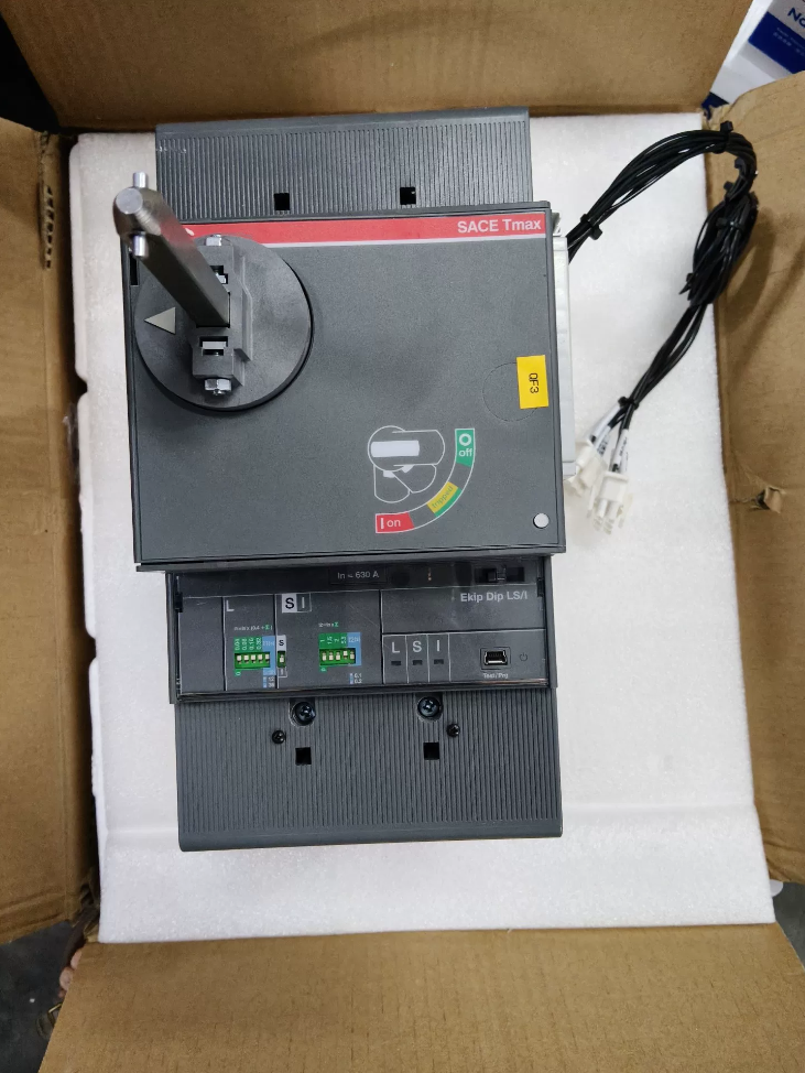

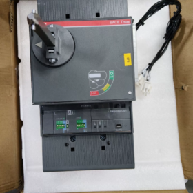
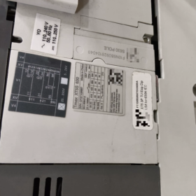
The АББ XT5S 630 - S-размыкающая способность MCCB с типоразмером 630 А из серии низковольтных автоматических выключателей в литом корпусе Tmax XT от ABB. В основном используется для защиты от перегрузки и короткого замыкания в системах распределения электроэнергии переменного тока низкого напряжения.. Компактность и высокая отключающая способность при коротком замыкании., он поддерживает несколько конфигураций расцепителей, включая термомагнитные и электронные типы.. Широко применяется в промышленном распределении электроэнергии., электроснабжение здания, центры обработки данных и другие сценарии, он соответствует IEC 60947-2 и ГБ/Т 14048.2 стандарты.
- Полная разбивка кодирования модели
Определение базовой модели
ХТ5 С 630
- ХТ5: Код рамки серии Tmax XT, номинальный ток корпуса варьируется от 400 А до 630 А
- С: Класс отключающей способности при коротком замыкании; предельная отключающая способность при коротком замыкании Icu = 50 кА при 415 В переменного тока
- 630: Номинальный ток корпуса 630А; Номинальный ток расцепителя In можно выбрать в пределах диапазона тока корпуса
Объяснение модели полного суффикса
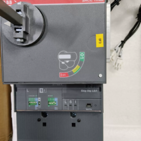
Возьмем базовую модель XT5S. 630 Ekip Dip LS/I In=630 3p F F` как пример:
Командный провал: Экономичный электронный расцепитель без дисплея, регулируется с помощью DIP-переключателей
ЛС/Я: Комбинированные функции защиты: л (долговременная защита от перегрузки) + С (защита от кратковременного короткого замыкания) + я (мгновенная защита от короткого замыкания) (3-защита сцены)
В=630: Номинальный рабочий ток расцепителя 630А
3п: 3-столб; 4-столб (4п) является необязательным
Ф Ф: Монтаж & тип проводки; первая F означает фиксированное крепление, вторая F для передней проводки
- Основные технические параметры
- Электрические параметры производительности
| Параметр Элемент | Спецификация Значение | Примечания |
| Номинальный ток корпуса Iu | 630А | Максимальный рейтинг кадров |
| Номинальный ток расцепителя In | 315А / 400А / 500А / 630А | Доступно несколько рейтингов, соответствие соответствующим моделям расцепителей |
| Номинальное рабочее напряжение Ue | 220 В~690 В переменного тока, 50/60Гц | Применимо для всего диапазона напряжений. |
| Предельная отключающая способность при коротком замыкании Icu | 415В и: 50тот | Стандартное значение для класса S |
| 690В и: 25тот | ||
| 250В Вашингтоне: 35тот (2 полюса последовательно) | ||
| Сервисные микросхемы отключающей способности при коротком замыкании | 415В и: 50тот | ИКС = 100% Ику, многоразовый после прерывания неисправности |
| Функции защиты | Длительная перегрузка, кратковременное короткое замыкание, мгновенное короткое замыкание, замыкание на землю (необязательный) | Зависит от типа расцепителя |
| Механическая выносливость | 20,000 рабочие циклы | В номинальных условиях |
| Рабочая частота | 240 циклов/час | Номинальная частота для электрического режима |
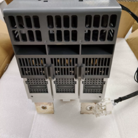
- Механический & Физические параметры
Вес единицы: Приблизительно. 5.6кг (3-полюс фиксированного типа)
Типы крепления: Зафиксированный, плагин, выдвижной
Типы проводки: Передняя проводка, задняя проводка, вставное шинное соединение
Степень защиты: IP20 для основного корпуса; возможность модернизации до IP40 с помощью крышек клемм
III. Сравнение классов отключающей способности для корпуса XT5
Различия в параметрах между классами отключающей способности при одном и том же типоразмере для упрощения повышения или понижения мощности.:
| Нарушение класса | Код | Icu при 415 В переменного тока | Типичные сценарии применения |
| Базовый | Н | 36тот | Гражданские здания, клеммные распределительные цепи |
| Стандартный | С | 50тот | Промышленные предприятия, главные входящие шкафы, общие силовые цепи |
| Высокий разрыв | ЧАС | 70тот | Низковольтная сторона трансформаторов большой мощности., системы с высоким током короткого замыкания |
- Выбор основных конфигураций расцепителей
XT5S 630 поддерживает два типа расцепителей: термомагнитные и электронные, для удовлетворения разнообразных требований защиты:
| Тип расцепителя | Код модели | Функции защиты | Метод регулировки | Сценарии применения |
| Термомагнитный расцепитель | ТМА | 2-защита сцены: Л давний + я мгновенно | Поворотная ручка / DIP-переключатель | Общее распределение мощности, защита двигателя, экономически эффективный |
| Экономичный электронный расцепитель | Командный провал | 3-ступень защиты LS/I | DIP-переключатели | Системы распределения, требующие выборочной координации между вышестоящими и нижестоящими устройствами. |
| Высококлассный интеллектуальный расцепитель | Команда Touch | 4-этап защиты LSIG + учет энергии | Сенсорные кнопки + экран дисплея | Интеллектуальное распределение мощности, сценарии, требующие регистрации неисправностей и мониторинга энергии |
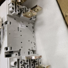
- Типы монтажа & Характеристики проводки
- Типы монтажа
Зафиксированный (ПН/ПТ): Передняя/задняя проводка, непосредственно фиксируется винтами, самая низкая стоимость, для стационарных распределительных шкафов
Плагин (ПМП): Установка вставной шины, поддерживает быструю замену, для выдвижного распределительного устройства
Выкатной (ВМП): Оборудован выдвижным механизмом., очистить точки останова изоляции, для главных цепей, требующих частого обслуживания
- Характеристики проводки кабеля (Справочник по медному кабелю)
In=630А: Рекомендуется 2 параллельные одножильные медные кабели сечением 240 мм², или медная шина 60×6 мм.
In=500А: Рекомендуется 1 одножильный медный кабель сечением 300 мм², или медная шина 50×5 мм.
- Сравнение эквивалентных моделей разных брендов
Эталонные альтернативные модели массового спроса с идентичным типоразмером 630 А и отключающей способностью 50 кА.:
| Бренд | Эквивалентная модель | Ток кадра | Отключающая способность при 415 В переменного тока | Описание совместимости |
| Шнайдер Электрик | NSX630S | 630А | 50тот | Функционально эквивалент; другие размеры монтажного выреза, требующие модификации шкафа |
| Сименс | 3ВЛ630С | 630А | 50тот | Стабильная защита; характеристики терминала различаются |
| Чинт | НМ1-630С | 630А | 50тот | Экономически эффективная отечественная альтернатива; невзаимозаменяемые монтажные размеры |
VII. Типичные сценарии применения
- Главные вводные выключатели и шиносоединители для низковольтных распределительных систем
- Защита главной цепи для силовых нагрузок большой мощности (водяные насосы, фанаты, компрессоры)
- Защита распределения электроэнергии для промышленных производственных линий, дата-центры и коммерческие комплексы
- Защита со стороны постоянного тока для новых энергетических систем, таких как фотоэлектрические системы и накопители энергии. (со специальным расцепителем постоянного тока в качестве опции)
VIII. Матрица обработки общих неисправностей
| Категория неисправности | Типичное явление неисправности | Анализ первопричин | Пошаговые решения |
| Механические неисправности в работе | Автоматический выключатель не может замкнуться; ручка отскакивает сразу после отпускания при нажатии в сторону ВКЛ. | 1. Неполный сброс после срабатывания неисправности (наиболее частая причина) | 1. Сильно потяните ручку полностью вниз в самое нижнее положение ВЫКЛ, пока не услышите щелчок сброса., затем замкни выключатель |
| (Чаще всего на месте) | 2. Катушка отключения минимального напряжения обесточена / недостаточное напряжение блокировки механизма | 2. Измерьте напряжение питания катушки минимального напряжения, чтобы подтвердить соответствие номинальному значению. | |
| 3. Блокированные внешние электрические или механические блокировки | 3. Проверка внешних сигналов, включая блокировку двери шкафа и противопожарную блокировку., затем отпустите замки | ||
| 4. Контактная сварка и заклинивание механизма после прерывания КЗ | 4. Если контактная сварка подтверждена, не закрывайте принудительно; заменить весь выключатель напрямую | ||
| Тяжелый, заедает работа ручки с неплавным переключением передач | 1. Механизм забит пылью и смазкой., недостаточная смазка на вращающихся валах | 1. Очистите механизм от пыли и нанесите небольшое количество изоляционной смазки на вращающиеся валы. | |
| 2. Деформация корпуса, сжимающая корпус и смещающая механизм | 2. Отрегулируйте крепежные винты, чтобы устранить нагрузку на корпус. | ||
| 3. Помехи от удлинителя внешней ручки или защитной крышки | 3. Снимите внешнюю крышку для проверки и исправления положения пересечения. | ||
| Аномальное непреднамеренное отключение | Непровоцированное отключение при небольшой нагрузке или при отсутствии нагрузки без очевидного короткого замыкания. | 1. Настройка длительной защиты ниже фактического рабочего тока | 1. Проверьте фактический ток нагрузки и выполните сброс устройства длительного тока. |
| (Самый высокий процент жалоб пользователей) | 2. Температура окружающей среды выше 40°C, вызывающая тепловой дрейф термомагнитного расцепителя и преждевременное срабатывание. | 2. Выбирайте модели с коэффициентами снижения мощности для работы в условиях высоких температур или переходите на корпус с более высоким номинальным током. | |
| 3. Сильный гармонический ток в системе, вызывающий дополнительный нагрев проводника и срабатывание защиты | 3. Снижение гармоник в системе путем установки реакторов или фильтров активной мощности. | ||
| 4. Старение компонентов расцепителя с дрейфом параметров | 4. Замените расцепитель, если на термомагнитных типах наблюдается сильный тепловой дрейф. | ||
| Мгновенное отключение при запуске двигателей или инверторов. | 1. Слишком низкая уставка мгновенной защиты, неспособная выдержать пусковой пусковой ток. | 1. Установите множитель мгновенной защиты на 8~10In для цепей двигателя. | |
| 2. Слишком короткая кратковременная задержка защиты без запаса на переходные процессы при запуске. | 2. Включите функцию кратковременной задержки и установите задержку 0,1–0,4 с для обхода пикового тока при запуске. | ||
| 3. Motor-specific trip unit is recommended for dedicated motor circuits | |||
| Frequent earth fault tripping on models with earth fault protection | 1. Total normal leakage current of the system exceeds protection setting | 1. Measure actual system leakage current and moderately raise earth fault trip threshold | |
| 2. Incorrect N-line wiring or reversed polarity on 4-pole breakers | 2. Correct N-line wiring to ensure it passes through the zero-sequence CT | ||
| 3. Zero-sequence CT installed at wrong position | 3. Install zero-sequence CT in accordance with manual specifications | ||
| Trip Unit Malfunction | Black screen and unresponsive buttons on Ekip Touch electronic trip unit | 1. Auxiliary control power supply disconnected or lost | 1. Check auxiliary power wiring and voltage rating (220 В переменного тока / 24 В постоянного тока, и т. д.) |
| 2. Loose plug connection between trip unit module and main body | 2. Подключите модуль расцепителя после отключения питания, чтобы обеспечить полный контакт контактов. | ||
| 3. Повреждены электронные компоненты внутри расцепителя защиты. | 3. Замените расцепитель идентичной модели, если модуль поврежден. | ||
| Расцепитель Ekip Dip с DIP-переключателем не применяет настроенные параметры | 1. DIP-переключатели не полностью заблокированы в критических положениях | 1. Переключите DIP-переключатели после отключения питания и убедитесь, что каждая передача полностью включена. | |
| 2. Плохой контакт трансформаторов тока расцепителя | 2. Переустановите расцепитель, чтобы обеспечить плотную посадку между трансформатором тока и основным корпусом. | ||
| Нет индикации неисправности или сохраненных записей после срабатывания неисправности. | 1. Потеря вспомогательного питания на расцепителе, что приводит к потере данных о неисправности. | 1. Для расцепителей в критических цепях рекомендуется постоянный вспомогательный источник питания. | |
| 2. Индикатор застрявшей механической неисправности не выскакивает | 2. Вручную перезапустите механизм индикатора и проверьте детали рычажного механизма. | ||
| Аксессуар & Неисправности вспомогательной цепи | Катушки шунтового расцепителя и расцепителя минимального напряжения не срабатывают. | 1. Несоответствие номинального напряжения катушки и напряжения питания | 1. Проверьте этикетку напряжения катушки и замените ее на соответствующую спецификацию. |
| 2. Ослабленная проводка или разрыв цепи из-за сгоревшей катушки. | 2. Измерьте целостность катушки мультиметром.; замените катушку, если сгорела | ||
| 3. Недостаточный ход толкателя катушки, не позволяющий привести в действие механизм | 3. Отрегулируйте положение установки катушки, чтобы гарантировать достаточный ход толкателя. | ||
| Неправильный сигнал и плохой контакт вспомогательных контактов | 1. Изношенные и окисленные серебряные контакты вспомогательных контактов. | 1. Замените модуль вспомогательных контактов. | |
| 2. Смещенный рычаг связи приводит к неполному переключению контактов | 2. Отрегулируйте положение рычажного механизма, чтобы обеспечить надежное переключение контактов при закрытии и открытии. | ||
| Перегрев & Неисправности проводки | Перегретые входящие/исходящие клеммы, горячая оболочка со специфическим запахом | 1. Винты клемм не затянуты с указанным моментом, что приводит к чрезмерному контактному сопротивлению. | 1. Затяните клеммы с моментом, указанным производителем. (приблизительно. 25~30 Н·м для клемм 630 А) |
| 2. Недостаточное сечение кабеля приводит к длительному нагреву при перегрузке. | 2. Замените кабели большего сечения или добавьте больше параллельных кабелей. | ||
| 3. Неравномерная длина кабеля среди параллельных кабелей приводит к несбалансированному распределению тока. | 3. Убедитесь, что параллельные кабели имеют одинаковую длину., спецификация и клеммы | ||
| 4. Прямое соединение медь-алюминий вызывает электрохимическую коррозию. | 4. Установите медно-алюминиевые переходные проушины.; прямое соединение медь-алюминий запрещено | ||
| Общий перегрев корпуса гидромолота | 1. Длительная работа с превышением номинального тока | 1. Ограничьте ток нагрузки или перейдите на корпус большего размера. | |
| 2. Плохая вентиляция шкафа и слишком высокая температура окружающей среды. | 2. Добавьте вентиляторы охлаждения шкафа для улучшения вентиляции. | ||
| 3. Износ главных контактов приводит к увеличению контактного сопротивления. | 3. Замените весь выключатель, если сопротивление контакта превышает стандартные пределы. | ||
| Неисправности после короткого замыкания | Невозможно включить выключатель после прерывания короткого замыкания.; механизм заблокирован | 1. Ток короткого замыкания системы превышает номинальную отключающую способность выключателя, вызывая контактную сварку | 1. Проверьте ток короткого замыкания системы и замените его на более высокий класс отключения. (например. Класс Н) модель |
| 2. Механизм деформирован от удара и заклинило расцепляющий вал. | 2. Замените весь выключатель, если механизм поврежден.; разборка и ремонт запрещены | ||
| Снижение утечек в изоляции и шкафу после устранения неисправности. | 1. Дуговая абляция дуговой камеры приводит к образованию карбидных отложений на изолирующих деталях. | 1. Снимите съемную дугогасительную камеру., очистите угольный порошок и установите на место после полного высыхания | |
| 2. Внутренняя изоляционная перегородка повреждена горением дуги | 2. Замените весь выключатель, если изолирующие компоненты повреждены. |
Распространенные неисправности & Решения для ABB XT5S 630
Неисправности поля ABB XT5S 630 MCCB в основном делятся на четыре категории: механические неисправности в работе, ненормальное срабатывание, выход из строя аксессуара и чрезмерное повышение температуры. Большинство проблем возникает из-за неправильной установки. & параметр, неподходящая рабочая среда или отсутствие регулярного технического обслуживания, при этом присущие заводские дефекты агрегата встречаются редко. Ниже приведен полный обзор частых неисправностей и соответствующих решений.:
Матрица обработки общих неисправностей
| Категория неисправности | Типичное явление неисправности | Анализ первопричин | Пошаговые решения |
| Механические неисправности в работе | Автоматический выключатель не может замкнуться; ручка отскакивает сразу после отпускания при нажатии в сторону ВКЛ. | 1. Неполный сброс после срабатывания неисправности (наиболее частая причина) | 1. Сильно потяните ручку полностью вниз в самое нижнее положение ВЫКЛ, пока не услышите щелчок сброса., затем замкни выключатель |
| (Чаще всего на месте) | 2. Катушка отключения минимального напряжения обесточена / недостаточное напряжение блокировки механизма | 2. Измерьте напряжение питания катушки минимального напряжения, чтобы подтвердить соответствие номинальному значению. | |
| 3. Блокированные внешние электрические или механические блокировки | 3. Проверка внешних сигналов, включая блокировку двери шкафа и противопожарную блокировку., затем отпустите замки | ||
| 4. Контактная сварка и заклинивание механизма после прерывания КЗ | 4. Если контактная сварка подтверждена, не закрывайте принудительно; заменить весь выключатель напрямую | ||
| Тяжелый, заедает работа ручки с неплавным переключением передач | 1. Механизм забит пылью и смазкой., недостаточная смазка на вращающихся валах | 1. Очистите механизм от пыли и нанесите небольшое количество изоляционной смазки на вращающиеся валы. | |
| 2. Деформация корпуса, сжимающая корпус и смещающая механизм | 2. Отрегулируйте крепежные винты, чтобы устранить нагрузку на корпус. | ||
| 3. Помехи от удлинителя внешней ручки или защитной крышки | 3. Снимите внешнюю крышку для проверки и исправления положения пересечения. | ||
| Аномальное непреднамеренное отключение | Непровоцированное отключение при небольшой нагрузке или при отсутствии нагрузки без очевидного короткого замыкания. | 1. Настройка длительной защиты ниже фактического рабочего тока | 1. Проверьте фактический ток нагрузки и выполните сброс устройства длительного тока. |
| (Самый высокий процент жалоб пользователей) | 2. Температура окружающей среды выше 40°C, вызывающая тепловой дрейф термомагнитного расцепителя и преждевременное срабатывание. | 2. Выбирайте модели с коэффициентами снижения мощности для работы в условиях высоких температур или переходите на корпус с более высоким номинальным током. | |
| 3. Сильный гармонический ток в системе, вызывающий дополнительный нагрев проводника и срабатывание защиты | 3. Снижение гармоник в системе путем установки реакторов или фильтров активной мощности. | ||
| 4. Старение компонентов расцепителя с дрейфом параметров | 4. Замените расцепитель, если на термомагнитных типах наблюдается сильный тепловой дрейф. | ||
| Мгновенное отключение при запуске двигателей или инверторов. | 1. Слишком низкая уставка мгновенной защиты, неспособная выдержать пусковой пусковой ток. | 1. Отрегулируйте множитель мгновенной защиты на 8~10″In для цепей двигателя. | |
| 2. Слишком короткая кратковременная задержка защиты без запаса на переходные процессы при запуске. | 2. Включите функцию кратковременной задержки и установите задержку 0,1–0,4 с для обхода пикового тока при запуске. | ||
| 3. Motor-specific trip unit is recommended for dedicated motor circuits | |||
| Frequent earth fault tripping on models with earth fault protection | 1. Total normal leakage current of the system exceeds protection setting | 1. Measure actual system leakage current and moderately raise earth fault trip threshold | |
| 2. Incorrect N-line wiring or reversed polarity on 4-pole breakers | 2. Correct N-line wiring to ensure it passes through the zero-sequence CT | ||
| 3. Zero-sequence CT installed at wrong position | 3. Install zero-sequence CT in accordance with manual specifications | ||
| Trip Unit Malfunction | Black screen and unresponsive buttons on Ekip Touch electronic trip unit | 1. Auxiliary control power supply disconnected or lost | 1. Check auxiliary power wiring and voltage rating (220 В переменного тока / 24 В постоянного тока, и т. д.) |
| 2. Loose plug connection between trip unit module and main body | 2. Подключите модуль расцепителя после отключения питания, чтобы обеспечить полный контакт контактов. | ||
| 3. Повреждены электронные компоненты внутри расцепителя защиты. | 3. Замените расцепитель идентичной модели, если модуль поврежден. | ||
| Расцепитель Ekip Dip с DIP-переключателем не применяет настроенные параметры | 1. DIP-переключатели не полностью заблокированы в критических положениях | 1. Переключите DIP-переключатели после отключения питания и убедитесь, что каждая передача полностью включена. | |
| 2. Плохой контакт трансформаторов тока расцепителя | 2. Переустановите расцепитель, чтобы обеспечить плотную посадку между трансформатором тока и основным корпусом. | ||
| Нет индикации неисправности или сохраненных записей после срабатывания неисправности. | 1. Потеря вспомогательного питания на расцепителе, что приводит к потере данных о неисправности. | 1. Для расцепителей в критических цепях рекомендуется постоянный вспомогательный источник питания. | |
| 2. Индикатор застрявшей механической неисправности не выскакивает | 2. Вручную перезапустите механизм индикатора и проверьте детали рычажного механизма. | ||
| Аксессуар & Неисправности вспомогательной цепи | Катушки шунтового расцепителя и расцепителя минимального напряжения не срабатывают. | 1. Несоответствие номинального напряжения катушки и напряжения питания | 1. Проверьте этикетку напряжения катушки и замените ее на соответствующую спецификацию. |
| 2. Ослабленная проводка или разрыв цепи из-за сгоревшей катушки. | 2. Измерьте целостность катушки мультиметром.; замените катушку, если сгорела | ||
| 3. Недостаточный ход толкателя катушки, не позволяющий привести в действие механизм | 3. Отрегулируйте положение установки катушки, чтобы гарантировать достаточный ход толкателя. | ||
| Неправильный сигнал и плохой контакт вспомогательных контактов | 1. Изношенные и окисленные серебряные контакты вспомогательных контактов. | 1. Замените модуль вспомогательных контактов. | |
| 2. Смещенный рычаг связи приводит к неполному переключению контактов | 2. Отрегулируйте положение рычажного механизма, чтобы обеспечить надежное переключение контактов при закрытии и открытии. | ||
| Перегрев & Неисправности проводки | Перегретые входящие/исходящие клеммы, горячая оболочка со специфическим запахом | 1. Винты клемм не затянуты с указанным моментом, что приводит к чрезмерному контактному сопротивлению. | 1. Затяните клеммы с моментом, указанным производителем. (приблизительно. 25~30 Н·м для клемм 630 А) |
| 2. Недостаточное сечение кабеля приводит к длительному нагреву при перегрузке. | 2. Замените кабели большего сечения или добавьте больше параллельных кабелей. | ||
| 3. Неравномерная длина кабеля среди параллельных кабелей приводит к несбалансированному распределению тока. | 3. Убедитесь, что параллельные кабели имеют одинаковую длину., спецификация и клеммы | ||
| 4. Прямое соединение медь-алюминий вызывает электрохимическую коррозию. | 4. Установите медно-алюминиевые переходные проушины.; прямое соединение медь-алюминий запрещено | ||
| Общий перегрев корпуса гидромолота | 1. Длительная работа с превышением номинального тока | 1. Ограничьте ток нагрузки или перейдите на корпус большего размера. | |
| 2. Плохая вентиляция шкафа и слишком высокая температура окружающей среды. | 2. Добавьте вентиляторы охлаждения шкафа для улучшения вентиляции. | ||
| 3. Износ главных контактов приводит к увеличению контактного сопротивления. | 3. Замените весь выключатель, если сопротивление контакта превышает стандартные пределы. | ||
| Неисправности после короткого замыкания | Невозможно включить выключатель после прерывания короткого замыкания.; механизм заблокирован | 1. Ток короткого замыкания системы превышает номинальную отключающую способность выключателя, вызывая контактную сварку | 1. Проверьте ток короткого замыкания системы и замените его на более высокий класс отключения. (например. Класс Н) модель |
| 2. Механизм деформирован от удара и заклинило расцепляющий вал. | 2. Замените весь выключатель, если механизм поврежден.; разборка и ремонт запрещены | ||
| Снижение утечек в изоляции и шкафу после устранения неисправности. | 1. Дуговая абляция дуговой камеры приводит к образованию карбидных отложений на изолирующих деталях. | 1. Снимите съемную дугогасительную камеру., очистите угольный порошок и установите на место после полного высыхания | |
| 2. Внутренняя изоляционная перегородка повреждена горением дуги | 2. Замените весь выключатель, если изолирующие компоненты повреждены. |
Ключевые моменты для предотвращения неисправностей & Регулярное техническое обслуживание
- Перед вводом в эксплуатацию затяните клеммы проводов строго с номинальным моментом затяжки.; проверка сопротивления контактов рекомендуется для сильноточных цепей.
- Заранее выберите пониженную мощность для сред с высокой температурой., высокая влажность или сильная пыль; регулярно очищайте пыль, скопившуюся на поверхности выключателя.
- Для цепей электронного расцепителя рекомендуется использовать постоянный вспомогательный источник питания, чтобы избежать потери записей о неисправностях..
- Ежегодно проводите как минимум одно испытание на механическое функционирование, чтобы убедиться в плавности закрытия и открытия.; ручное открытие при большой нагрузке запрещено.
- Проверяйте состояние контактов после каждого прерывания короткого замыкания.; немедленно замените весь блок по достижении предельного срока службы электрооборудования..


 из серии Schneider TeSys GV2. Он имеет регулируемую настройку тока 24-32А.,")

")


NH42-63-318x560.png "Автоматические переключатели резерва типа PC CHINT (АТС)НХ42-63/4СЗ")


