 Контактор,автоматический выключатель,датчик,Кодер,ПЛК,Конвертер

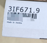

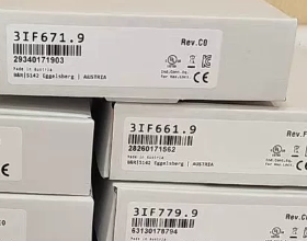
ПРОФИБУС ДП communication interface module for the System 2005 ряд
(Exclusive to legacy System 2005 rack CPUs, конец жизни)
- Official Standard Description
Система 2005 interface module with 1 galvanically isolated RS485 port supporting PROFIBUS DP fieldbus; installed in the IF expansion slot between the CPU and additional expansion slots.
- Разбивка кода модели
| Сегмент | Определение |
| 3ЕСЛИ | Communication interface module family for System 2005 |
| 661 | PROFIBUS DP galvanically isolated RS485 interface sub-series |
| 0.9 | Номер версии оборудования |
- Основное оборудование & Электрические параметры (Оригинальный паспорт)
- Шинный интерфейс
Physical layer: 1 galvanically isolated RS485 channel (PROFIBUS-compliant)
Isolation withstand voltage: 250 V AC galvanic isolation for enhanced on-site EMC immunity
Matching connector: 0G1000.00-090 standard PROFIBUS bus terminal (optional accessory)
- Communication Specifications
Протокол: ПРОФИБУС ДП (Сорт 1 Master only)
Скорость передачи данных: Adaptive range from 9.6 kbit/s to 12 Мбит/с
Station address range: 0 ~ 126
Supporting file: Official GSD file package V1.01 for 3IF661.9
- Источник питания & Потребляемая мощность
Источник питания: Derived from System 2005 объединительная шина; no external 24 VDC power required
Типичное энергопотребление: 0.4 Вт
- Экологические рейтинги
Рабочая температура: -20 ℃ ~ +60 ℃
Хранилище / температура транспортировки: -40 ℃ ~ +85 ℃
Класс защиты: IP20 (cabinet-mount only)
Масса: Приблизительно. 0.10 кг
- Сертификаты
CE, UKCA, UL cULus, EAC industrial control certifications
III. Установка & Инструкции по настройке
- Rack Mounting Rules
Compatible only with System 2005 series CPU racks (3CPxxx, 3RPxxx controllers)
Монтажное положение: First IF expansion slot on the right side of the CPU; IO slots are prohibited
Maximum quantity per CPU: 1 piece of 3IF661.9
- Software Support
Программное обеспечение для программирования: Automation Studio
Minimum compatible version: AS V4.0 (with hardware upgrade package 1.0.0.1)
Configurable items: DP station address, скорость передачи данных, process data mapping, diagnostic enable
- Диагностика
Module equipped with status LEDs for power supply, bus communication fault and DP bus disconnection diagnostics.
- End-of-Life Replacement Solutions (Система 2005 to X20 Migration)
Решение 1: Direct replacement within the same architecture (retaining System 2005 стойка, spare part procurement)
No compatible upgraded model in the same series. The 3IF661.9 has been officially discontinued; only used/refurbished spare parts are available.
Решение 2: Full system upgrade to X20 (Рекомендуется для новых проектов. & retrofits)
| Original System 2005 Модуль | X20 Replacement Model | Описание разницы |
| 3ИФ661.9 (Galvanically isolated PROFIBUS DP RS485 Master) | X20IF1061 | PROFIBUS DP Master for X20 racks, galvanically isolated with improved performance |
| X20IF1063 | Dual-channel PROFIBUS DP for redundant bus applications |
Примечания по замене
- Система 2005 programs cannot be migrated directly to X20; hardware configuration, bus mapping and compilation must be reworked.
- PROFIBUS GSD files are fully compatible, no modifications required for DP slave devices.
- Объединительная шина, power supply and mounting dimensions are completely incompatible; full replacement of X20 CPU + base unit is mandatory.
- Типичные сценарии применения
Станки & упаковочное оборудование: Legacy System 2005 Б&R PLCs communicating with inverters, servo drives and remote DP IO stations
Production line retrofits: PROFIBUS bus communication expansion for aging equipment
Металлургия, пластик & textile legacy automation line communication capacity expansion
- Матрица поиска и устранения распространенных неисправностей
| Явление неисправности | Первопричина | Шаги разрешения |
| BUS LED solid red, нет связи | Disconnected DP bus / отсутствует оконечный резистор | 1. Check termination DIP switch on 0G1000 bus connector; 2. Measure continuity of A/B signal lines; 3. Verify duplicate station addresses |
| Нет светодиодной подсветки после включения питания | Poor contact in backplane slot | Remove and reinsert the module, clean gold fingers of backplane, test in alternate IF slot |
| Frequent communication packet loss | Плохое заземление / damaged isolation circuit | Separate routing of power cables and DP bus cables; replace the 3IF661.9 module |
VII. Supporting Document List (Official Downloadable)
- Datasheet 3IF661.9 V1.0 (2004 English manual)
- AS V4.0 hardware upgrade firmware package
- PROFIBUS GSD description file package V1.01
- 0G1000.00-090 bus connector wiring manual
Complete Communication Parameter Configuration Tutorial for B&R 3IF661.9 (System2005 PROFIBUS DP Master)
Предварительные условия
- Hardware Constraints
Compatible only with System2005 rack CPUs (3CPxxx/3RPxxx), installed in the IF communication slot to the right of CPU (IO slots forbidden); максимум 1 unit per CPU.
DP bus accessories: Standard 0G1000 DP connectors; set terminating resistor to ON for the first & last bus nodes, OFF for intermediate nodes.
- Программная среда
Automation Studio V4.0 ~ V4.7 (Hardware library for System2005 is removed in versions above V4.7)
System2005 full hardware library must be loaded; native driver for 3IF661.9 included, no separate module GSD import needed.
- File Preparation
GSD files for all DP slave devices (инверторы, remote IO, инструменты, и т. д.)
- Hardware Rack Configuration (Physical View)
- Create a new standard project and select the corresponding 3CP/3RP System2005 CPU.
- Switch to the Physical View hardware view on the left, drag and drop the CPU onto the rack.
- Drag and drop module `3IF661.9` into the IF expansion slot on the right of the CPU.
> Примечание: Slot position must match physical hardware; hardware mismatch error will be triggered during download otherwise.
- Right-click 3IF661.9 → Configuration to open the DP master parameter panel.
- Core DP Master Communication Parameter Settings (3IF661.9 Configuration)
- General Bus Parameters (General Tab)
| Параметр Элемент | Value Rule | Описание |
| Station address (Master Address) | 1~126, 0 запрещено | Адрес 0 is reserved for DP broadcast; master station must use unique address 1~126 across the whole network |
| Скорость передачи данных | 9.6k/19.2k/93.75k/187.5k /500k/1.5M/3M/6M/12M | Cable length limits: 12M=100m, 1.5M=200m, 500k=400m, 187.5k=1000m; All slaves must adopt identical baud rate as master |
| Target Rotation Time | Мин. 2 РС, recommended 5~20 ms | Bus data refresh cycle; click 【Adjust】 for automatic token ring optimization by software |
| Bus Watchdog | 100~5000 ms | Timeout threshold for alarm upon bus disconnection/communication loss; 500 ms recommended for field applications |
| Изоляция | Зафиксированный 250 В и (hardware hardwired, non-configurable) | Hardware-built galvanic isolation, no software adjustment required |
- Advanced Bus Control Parameters (Advanced Tab)
- Retry count: Retransmission times upon communication failure; по умолчанию = 3, приспосабливаться к 5 for high-interference environments.
- Gap factor: DP token gap; keep default value 10.
- Diagnostic enable: Check to activate slave diagnostic functions for fault code reading via PLC program.
- Sync/Freeze support: Check for motion control synchronization scenarios; uncheck for standard IO applications.
- Key Operation Mode Note
The 3IF661.9 acts as a Class 1 Мастер ДП, supporting cyclic IO data exchange only. Slave mode and direct cross-slave DX communication are not supported.
III. Import DP Slave GSD Files & Configure Slaves
- Top menu bar of AS: 【Tools】→【3rd Party Device Manager】(Third-party Device Manager)
- Click 【Import Fieldbus Devices】 to import all slave `.gsd` files.
- Return to the configuration window of 3IF661.9 and switch to the 【Topology】 bus topology tab.
- Locate imported DP slaves in the left hardware library, drag and drop onto the DP bus line.
- Double-click each slave to assign a unique station address (1~126), not overlapping with master address.
- Double-click the slave to access IO mapping page; select input/output byte length matching device datasheet.
- IO Process Data Mapping (I/O Mapping – Core PLC Program Interface)
- Switch to the 【I/O Mapping】 tab in the 3IF661.9 configuration window.
- DP_In (data received from slaves to PLC) & DP_Out (control commands sent from PLC to slaves) channels are displayed on the left.
- Bind global or program variables as shown below:
Inverter frequency setpoint: Bind `Program.DP_Out.Freq_Set` to Slave Output Byte 0~1
Motor current feedback: Bind `Program.DP_In.Motor_Current` to Slave Input Byte 2~3
- Mapping Rules
Set Consistency to All universally to prevent fragmented data misalignment
Maximum IO length per single slave shall not exceed 244 байты (DP standard limitation)
- Сборник, Скачать & Communication Diagnostics
- Download Workflow
- Click 【Apply】 to save module configuration after all parameters are set.
- Build the whole project; download to System2005 CPU if no hardware errors occur.
- Module LED Status Definition
PWR solid green: Backplane power supply normal
BUS flashing green: DP bus communication established normally
BUS solid red: Bus disconnection / duplicate address / mismatched baud rate
ERR solid red: Slave fault / mismatched IO mapping length
- Online Diagnostic Troubleshooting
- Open 【System Diagnostics Manager】 in online mode.
- Filter for the 3IF661.9 module to view:
Bus packet transmit/receive counters
List of offline/fault slave station numbers
Watchdog timeout & CRC communication error counters
- Rapid Fault Localization
All slaves offline: Проверьте скорость передачи данных, terminating resistors and A/B wiring
Single slave offline: Check hardware DIP station address, GSD IO PPO type and A/B wiring
- Распространенные ошибки конфигурации & Избежание ловушек
- Incorrect slot insertion: Installing 3IF661.9 into IO slot triggers hardware error during download.
- Duplicate station address: Master address = 1; slaves cannot use address 1; адрес 0 must not be assigned to any device.
- Несоответствующая скорость передачи данных: Any slave with inconsistent baud rate will result in solid red BUS LED and total communication loss.
- Missing/wrong GSD version: Slaves cannot be added or IO mapping table empty; reimport original manufacturer GSD file.
- Overly short cycle time: Target Rotation Time < 2 ms causes frequent packet loss and bus alarms.
- Chinese characters in project path: GSD import failure & compilation error; only English & numerals allowed in file paths.
VIII. Supplementary End-of-Life Migration Reference
The legacy System2005 rack-mounted 3IF661.9 cannot be used directly in X20 systems. Recommended upgrade replacement model: X20IF1061. Configuration logic is consistent, yet backplane and hardware library are fully incompatible, requiring full CPU & base unit replacement.
Complete List of B&R Communication Interface Modules
Classified by four major hardware platforms: Система 2005 (3ЕСЛИ, окончание срока действия), X20 (X20IF, mainstream cabinet PLC), х67 (X67IF/BC, IP67 distributed remote IO bus controllers), X90 (X90IF, mobile construction machinery). Categorized by fieldbus master/slave, serial port and real-time Ethernet bus.
- Система 2005 Series 3IF Communication Modules (Legacy Rack, Конец срока службы; 3IF661.9 belongs to this series)
Правило именования: `3IFxxx.9` = IF expansion slot communication module for System2005; suffix `.6`/`.86` for early hardware revisions.
- Серийный / Mixed Serial Modules
| Модель | Interface Specs | Приложение |
| 3IF613.9 | 3 galvanically isolated RS232 ports | Barcode scanners, инструменты, printer serial communication |
| 3ИФ621.9 | 1 galvanically isolated RS485/422 + 1 CAN port | Custom serial communication + CANopen |
| 3IF622.9 | 1 RS232 + 2 galvanically isolated RS485/422 ports | Multi-channel serial device interconnection |
- CAN Bus Series
| Модель | Interface Specs | Приложение |
| 3ИФ671.9 | RS232 + RS485 + 1 CAN port | Mixed serial & CAN expansion |
| 3ИФ672.9 | RS232 + 2 galvanically isolated CAN ports | Dual-channel CANopen Master |
- PROFIBUS DP Series (Your Current Module)
| Модель | Interface Specs | Режим работы |
| 3ИФ661.9 | 1 galvanically isolated RS485 DP port | Сорт 1 DP Master exclusive to System2005 racks |
| 3IF762.9 | RS485 + DP V0 Slave | DP Slave aPCI expansion card for CPU built-in aPCI slot |
- Ethernet / POWERLINK Ethernet в реальном времени
| Модель | Interface Specs | Функция |
| 3IF681.86 / 3IF681.95 / 3IF681.96 | 1×10M RJ45 Ethernet port | Standard TCP/IP HMI & upper computer communication |
| 3ИФ686.9 | Galvanically isolated POWERLINK V1/V2 | POWERLINK motion control Master |
- aPCI Expansion Communication Cards (3IF7xx, CPU internal aPCI slot)
3IF722.9 (Multi-channel serial ports), 3IF761.9 (Мастер ДП), 3IF789.9-1 (ПИТАНИЕ + Мастер связи X2X)
- X20 Series X20IF Communication Modules (Current Mainstream Cabinet PLC, System2005 Migration Replacement)
Правило именования: `X20IF1xxx` single-bus module; `X20IF2xxx` dual mixed-bus module.
- Serial Communication RS232/485
X20IF1020: 1 galvanically isolated RS232/422/485 port
X20IF1030: 2 independent galvanically isolated RS485 ports
- PROFIBUS DP Series (3IF661.9 Replacement Options)
| Модель | Режим | Описание |
| X20IF1061 | DP V1 Master | Single-channel DP Master, top replacement for 3IF661.9 |
| X20IF1063 | DP V1 Slave | PLC acts as DP slave communicating with third-party master |
| X20IF1063-1 | DP Slave with DTM diagnostic support | Enhanced version for equipment commissioning & Поиск неисправностей |
| X20IF1063-2 | Dual-channel redundant DP Slave | Redundant bus architecture applications |
- МОЖЕТ / CANopen
X20IF1072: Single galvanically isolated CAN Master port
X20IF2792: 1 CAN port + 1 X2X ссылка (remote IO expansion bus)
- POWERLINK Real-Time Motion Bus
X20IF1082: Single-channel POWERLINK with integrated 2-port hub, ring redundancy support
X20IF1082-2: Equipped with PRC high-speed synchronization (многоосное синхронное управление)
X20IF1086-2: Fiber-optic POWERLINK for long-distance high-noise environments
- PROFINET IO
X20IF10E3-1: PROFINET IO Device (Раб)
X20IF10E1: PROFINET IO Controller (Владелец)
- X2X Link Remote IO Expansion Bus
X20IF2772: Мастер связи X2X, drives X67 distributed IP67 modules
III. X67 Series: IP67 Distributed Remote IO Communication Units
Two categories: X67BC bus controllers, X67IF serial modules
- X67BC Bus Controllers (Integrated IO channels, direct fieldbus connection)
X67BC4321: CANopen bus controller
X67BC5321: DeviceNet bus controller
X67BC6321: PROFIBUS DP bus controller; suffix .L08/.L12 corresponds to M8/M12 connectors
X67BC7321: CAN IO bus controller
X67BC8321-1: POWERLINK bus controller
- X67IF Standalone Serial Communication Modules (IP67 field-mount for scanners & инструменты)
X67IF1121-1: Combined RS232/RS485 with onboard 2DI + 2DO digital channels
- X90 Mobile Control Platform X90IF Expansion Boards (Строительная техника, Vehicle Controllers)
X90IF730.04-00: 3 CAN ports + 1 RS485 port dedicated to mobile equipment
General X90IF expansion boards: Support CAN, RS485 and Ethernet; PROFIBUS/PROFINET unsupported
- Universal Model Code Decoding Rules (Quick Function Identification)
- Platform Prefix
3IF = System2005 (Legacy Rack, Конец срока службы)
X20IF = X20 Cabinet PLC Communication Module (Активный мейнстрим)
X67BC = IP67 Remote Bus Controller; X67IF = IP67 Serial Module
X90IF = Mobile Construction Machinery Controller Expansion Board
- Mid Digit Bus Identifier
66x = PROFIBUS DP
67x = CAN Bus
62x = RS485/232 Serial Port
68x = Ethernet / ПИТАНИЕ
1061/1063 = X20 PROFIBUS
108x = X20 POWERLINK
- Suffix Revision Code
.9 / .6 = System2005 Hardware Revision
-1 / -2 = X20/X67 Enhanced Function Version (Резервирование, Fiber Optic, Advanced Diagnostics)
- Cross-Platform Replacement Reference for 3IF661.9 (Retrofit Selection Cheat Sheet)
| Original End-of-Life Module | Upgrade Replacement Model | Platform Migration Note |
| 3ИФ661.9 (System2005 DP Master) | X20IF1061 | Full X20 CPU & rack replacement required; DP protocol fully compatible, GSD files reusable |





NH42-63-318x560.png "Автоматические переключатели резерва типа PC CHINT (АТС)НХ42-63/4СЗ")



